Edge Collective
Soil Monitoring System in Mead, Nebraska (USA)
Developing a system for capturing soil moisture measurements from a remote field site, using wifi, LoRa, and cellular communications.June 25, 2019
Project Goals
An Edge Collective client was looking to establish some baseline soil measurements around tree planting sites in order to begin to assess the impact of regenerative agriculture practices there; specifically, the impact of biochar on soil moisture.
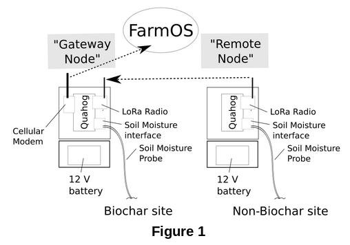
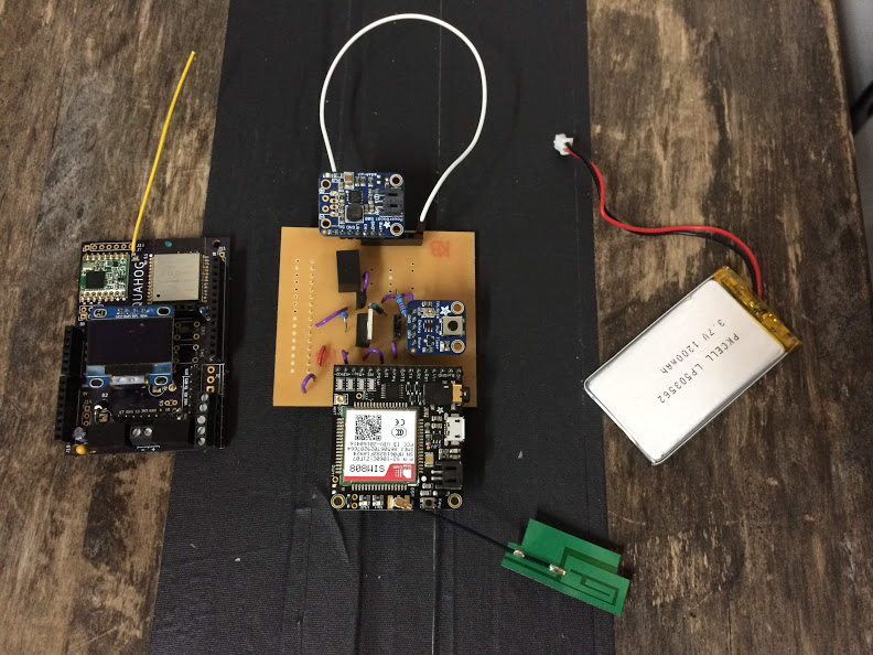
We're planning on beginning by creating two instrumentation setups, one at each measurement site (“biochar” and “non-biochar”). Each setup will operate on 12V battery power, and measure soil moisture and temperature locally every 30 minutes. One of the setups (“Remote Node”, Fig 1) will send its data to a “Gateway Node” via LoRa radio; and the “Gateway Node” will then send the combined datasets to FarmOS via cellular modem. We will be using HOBO / Decagon Soil Moisture probes as our sensors.
Cellular Posting to FarmOS
-- June 26, 2019, 18.00 --
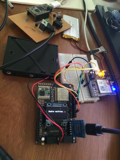
We'll begin by setting up a quick 'end-to-end' test system for transmitting data from a Quahog to FarmOS via a cellular modem (the Adafruit FONA cellular module).
Because the FONA can only use TSL 1.0, and FarmOS is setup to require higher than TSL 1.0 to POST, we'll be using a 'relay server' -- a very simple NodeJS script, farmos-relay, that receives POSTs from the FONA (accepting TSL 1.0) and then re-broadcasts to FarmOS. (Note: we should look into the security of doing things this way.)
-- Update, 18:55 --
I've reproduced the Quahog FONA code so that it posts to FarmOS via the above relay script. The micropython script is relay.py.
I've also got a Feather M0 LoRa running CircuitPython posting every second to the Quahog via LoRa; that code is called rad_alice.py
Next, to hook these up together so that the Feather is posting (fake, at this point, until I hook up the sensors) data to the Quahog, and then that data is posted to FarmOS. If I can get that running, I'll run it overnight at 30 minute intervals. It'd be nice to include a 1-wire sensor, or equivalent, if possible so that temperature data were collected. I'll see how far I can get ...
-- Update, 19:15 --
To make things easier, I'm rewriting the Feather LoRa code so that it'll just post (test) data once on boot, after two seconds. That code is here. That way when I want to test the remote --> gateway system, I can just press the "Reset" button the Feather, and after two seconds it'll send some test data through the system. At this point it's just CSV format data; in the future I'll try to send JSON and parse it on the other end.
-- Update, 19:43 --
I've got the Quahog receiving the Feather data via LoRa, and printing it out on the OLED, with this commit of rad_relay.py Micropython code on the Quahog.
-- Update, 20:06 --
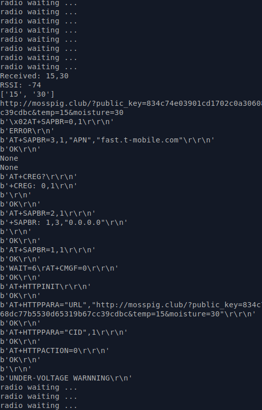
Cool! We've got the end-to-end demo (with faked data) now!
Remote Node -- (LoRa radio) --> Quahog -- (cellular) --> relay server --> FarmOS
The relevant code is this version of rad_relay.py on the Quahog.
TODO:
- Getting some temp data posted. I'll implement OneWire on the Feather side for this.
- Detecting the network status of the FONA and waiting until it's connected to attempt to post.
-- Update, 20:39 --
rad_onewire.py on the Feather will measure temp every interval, and post via LoRa ...
-- Update, 21.:01 --
Alright, looks like we're consistently posting -- with real temp data! The latest code is:
- Feather: rad_onewire.py (copied as main.py onto the Feather so that it runs on boot)
- Quahog: rad_relay.py
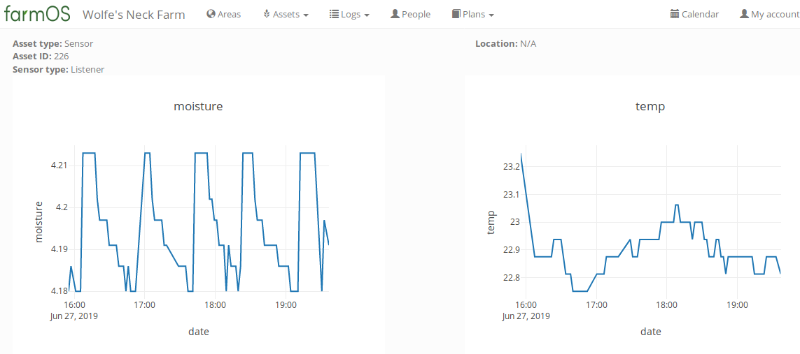
- FarmOS data: test data at the Wolfesneck FarmOS instance.
Still have the remaining todo:
- Detecting the network status of the FONA and waiting until it's connected to attempt to post.
-- June 27, 2019, 10:20 --
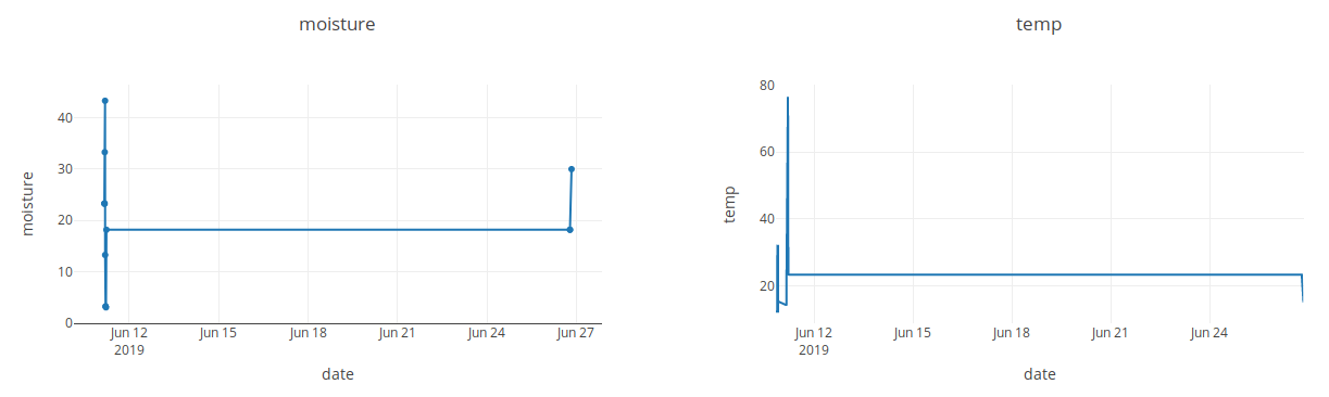
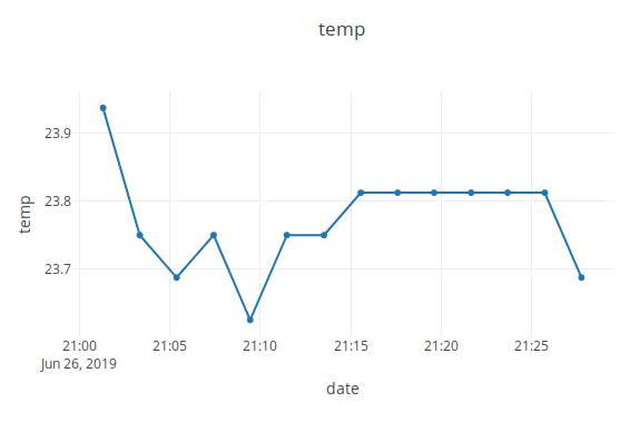
The cellular modem system has been running overnight without a hitch, posting temperature data every two minutes to FarmOS! I downloaded a csv file from FarmOS. Because the format is:
timestamp 1, key1, value1
timestamp 1, key2, value2
timestamp 2, key1, value1
tiemstamp 2, key2, value2
I used a little script I found online to remove every other line (so that I could focus on temp data only and graph it easily):
sed -e n\;d <file
Worked nicely. Plot of the resultant data (using LibreOffice) is here:
Cellular network status. I saw some notes online that the network status of the SIM800 module (on which the Fona is based) isn't particularly revealing about the actual network status. I'll at least try to assess its status, but not sure yet whether it makes sense to write any logic around it; it might be better to just attempt to send, and then if fail, go back to sleep -- rather than wasting battery on re-attempts. Perhaps the network status is reliable upon wakeup -- when it first transitions from "not available" to "available" -- in which case we can at least keep attempting to post before a TIMEOUT is reached.
Power. The next big step is to think about the optimal way to do battery power. The complication is that the FONA module really wants a 3.7V rechargeable battery input. What this might mean is that the rest of the system ought to get designed around that; or (less elegantly), that we have a separate charging system for the 3.7V battery, and then another one for the Quahog + sensor. The sensor will likely require 3.6 - 12V. The Quahog's 3.3V regulator requires 4.7V input, and its 5V regulator requires over 6V, I believe. Other than these voltage considerations, I believe the circuit for turning the entire system on and off is well-designed at this point; it's really just a matter of figuring out how to generate the required voltages nicely and simply.
-- Update 10:57 --
Okay, this might be a 'simple' solution: If I use a 5xAA battery pack, I get 5x1.5 volts = 7.5V input to the Quahog. This means that both the 3.3V and the 5V regulators on the Quahog will be happy. The 5V regulator output can then be used to recharge the 3.7V battery on the FONA (which has an onboard charger circuit). The question is whether I'll be charging it rapidly enough while the system is on to counteract the depletion due to FONA usage.
So a next step (which is necessary ultimately anyway) is to transmit the FONA battery voltage. I'll work on that today. That way we'll be able to check how we're doing on keeping that battery charged. Then power otherwise isn't as complicated.
Nice reference for the SIM800 module.
And here's a link to the SIM800 manual.
Specific information about the SIM800 battery command here.
-- Update 11:41 --
Okay! Was able to capture the cellular battery voltage using a function I slapped together, and made a new version of the Quahog code: rad_relay_batt.py.
I realized in the process that the "relay server" is currently "hard-coded" to accept and relay only two parameters: temp and soil moisture. So for this test, I'm just going to stuff the battery voltage into the moisture variable -- this will allow me to track the voltage values over time for a few hours. Meanwhile, I'll work on making the relay server on mosspig.club more generic if I can (perhaps making the cellular code into HTTP POST). And I'l also work on the power circuit.
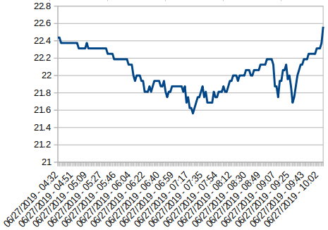
-- Update 20:34 --
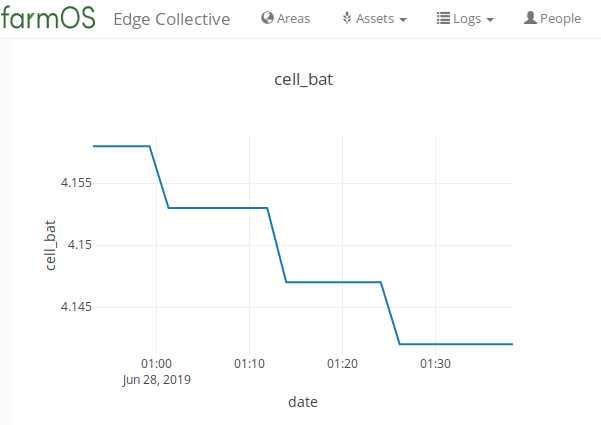
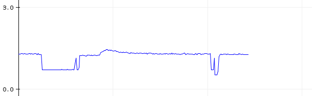
Okay, I've been running the cellular system for 24 hours straight, more or less; and keeping track of the cellular battery voltage for the last 10 or more. Here's a snapshot of the last 3 hours. It's what one would expect from a lithium ion battery charger: the battery discharges, the control circuit sees a threshold crossed and charges it back up again:
(And the temp has been going strong ...)
What I'd like to know is: what's a similarly 'clean' way of measuring voltage on other batteries? Whenever I've tried with a voltage divider, I've gotten such a noisy signal ... I'll look into it.
-- Update 23:48 --
I've swapped in a Ting mobile SIM card -- just involved changing the APN in Quahog code to "wholesale" instead of "fast.t-mobile.com" (for the previous T Mobile card I was using). Works nicely.
One option that might be easier around the "relay" code on the server is to simply accept an arbitrary number of additonal "GET" parameters. So then I don't have to worry about doing a "POST" on the SIM800 side -- I can just form a long GET url, and then construct a POST on the server side that will interact with FarmOS.
Next step: migrate from Wolfesneck FarmOS to Edge Collective FarmOS instance (deep thanks to Mike Stenta!).
-- Update Jun 28, 00:57 --
Neat! I've got the relay code on the server grabbing all of the GET params and posting them to FarmOS.
I've also migrated to the Edge Collective FarmOS instance. A next step might be to pass the FarmOS base url as a GET param, so that I don't have to touch the server code when migrating ...
-- Update 01:42 --
Things are running solidly now. I'm using the FarmOS base url as a GET param, as suggested above.
The relay code on the server side is relay_get_post.js, and the latest Quahog code is rad_relay_batt.py.
Next steps:
- See if I can resurrect the Iowa Decagon hardware;
- Look into the optimal power circuit for the Quahog + Cellular
- Add a "KEY" functionality to the cellular modem code to make sure it resets properly on boot
- Resurrect the timer circuit
Power circuit
-- Update June 29, 22:55 --
Okay, today I:
- Resurrected the timer circuit, and incorporated it.
- Figured out what (I think) is a workable power circuit that only requires one rechargeable battery
- Simply connected the 'KEY' pin to ground, which seems to work nicely with the power circuit
- Added in the 'DONE' timer functionality
- redid the LoRa antennae on each device
I'm connecting the 3.7V battery to the FONA directly; and I'm then using the solar charging circuit directly on the "BAT" pin of the FONA. This isn't crazy if one looks at the FONA schematic; as long as I don't apply power to '5V / USB in' on the FONA, I'm not powering its charger chip -- so I should be fine charging it on my own.
Oddly -- I would think that I ought to be able to connect the battery to the "BATT" JST on the solar lipo, and that this would be equivalent. But this didn't seem to work -- the FONA kept resetting. So, instead I'm running wires from the "B" pin on the solar lipo into the "BAT" pin on the FONA. Could it be the length of the wires? I should check the solar charger schematic to see why this might be the case.
-- Update June 30, 22:02 --
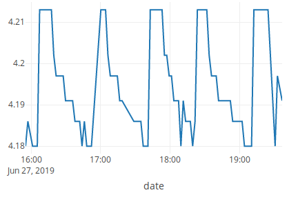
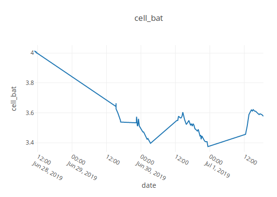
Tested circuit -- it works! It recharged during the sunlight hours today. Given the specs on the FONA, it won't work with a battery voltage below 3.4V, so it simply shuts down when that happens.
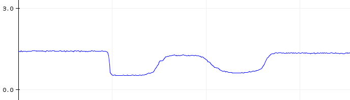
After I recharged today, here's a picture of the battery recharging again in the sun, then draining in the dark:
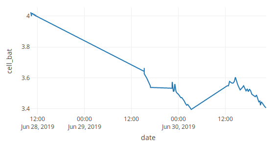
Once it drains down to 3.4V, it will stop.
There are two ways of mitigating this:
- select a larger lithium-ion battery, with greater capacity, and hope for more sun;
- have a way to introduce a battery backup, like a car battery.
So I've arranged to do both!
The circuit thus far is here:
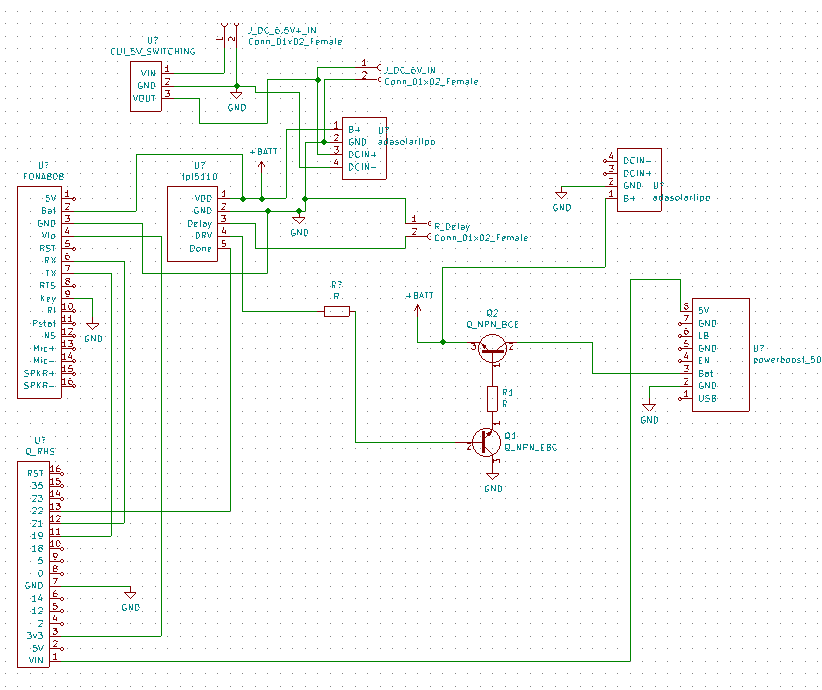
Need to look up adafruit solar lipo schematic to see what USB in does, how it relates to DCIN. Done: looks like there's a limiting resistor on the USB input. Might want to stick that in. (Done).
I'm using a 5V switching regulator (datasheet) that can take 36V input in the board design.
So, TODO over the next couple of days:
- make a milled board for the Gateway circuit
- work on connected the Decagon soil moisture sensors to the Feather side of things (will require rewriting the Gateway code, too)
- prototype the remote instrument with the timer chip included
- design a milled board for the Remote instrument (including a solar panel?)
- Order a larger lithium ion battery or two
Aside: the relay server, as written, is also useful for the satellite modem. It'll be fun to prototype that in the future.
Note: it'd be more generally useful if I swap over the regular SIM 800 FONA board. That'll require a little hot glue tomorrow.
-- Update Jul 1st, 2019, 18.31 --
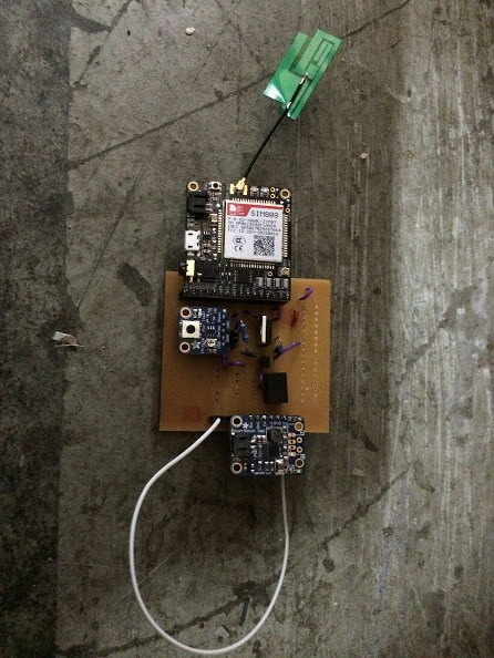
Spent the afternoon at artisan's prototyping the cellular gateway circuit:

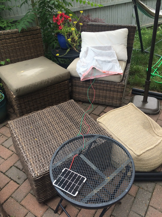
For now, I'm simply taping the pieces into a cardboard box in order to test them:
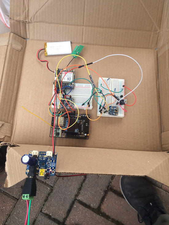
It was raining yesterday in between bouts of sunshine, so I used a low-tech solution -- a trashbag:
Meanwhile, while at Artisan's I found a nice spare project box for outdoor use:
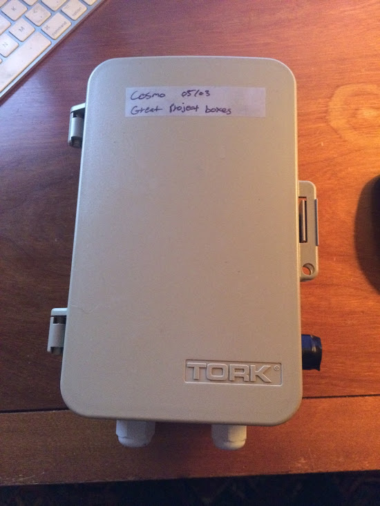
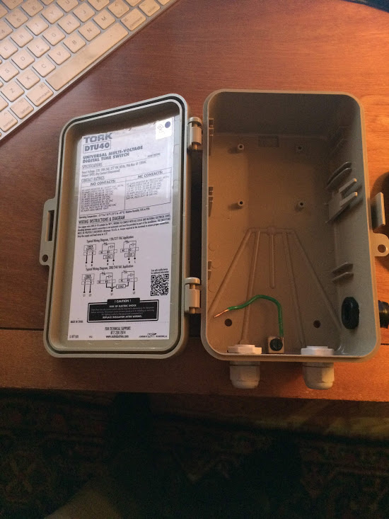
Doesn't seem to have rubber gaskets, but should be fine for at least the initial prototyping.
The solar charging setup is working. The battery is relatively low capacity -- 1200 mAH, compared to ~6000 mAH available on Adafruit -- and I haven't been keeping it outdoors in the mornings, so the pattern now is: it charges enough to work, and then discharges after sunset until it's no longer working. Then, when there's sunlight again, it comes back on. (You can see that in the below graph of cellular battery voltage over time.) I'll try a larger battery; but I've also designed the adapter circuit to allow for 6.5-36V input that will charge the solar battery and provide its own power.
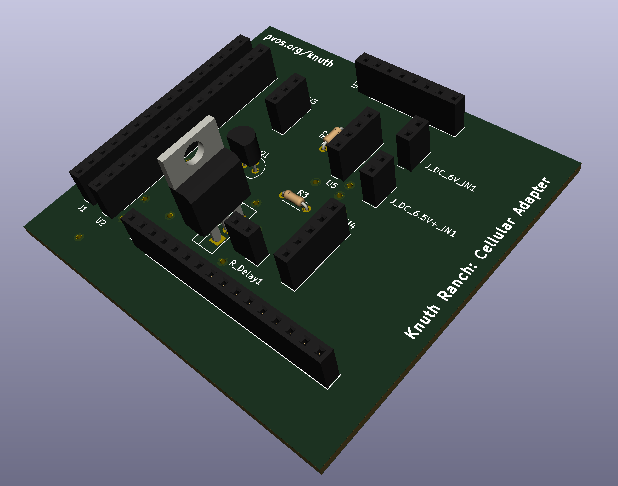
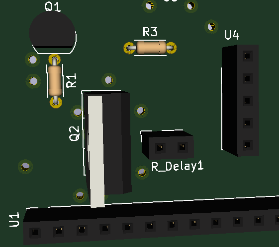
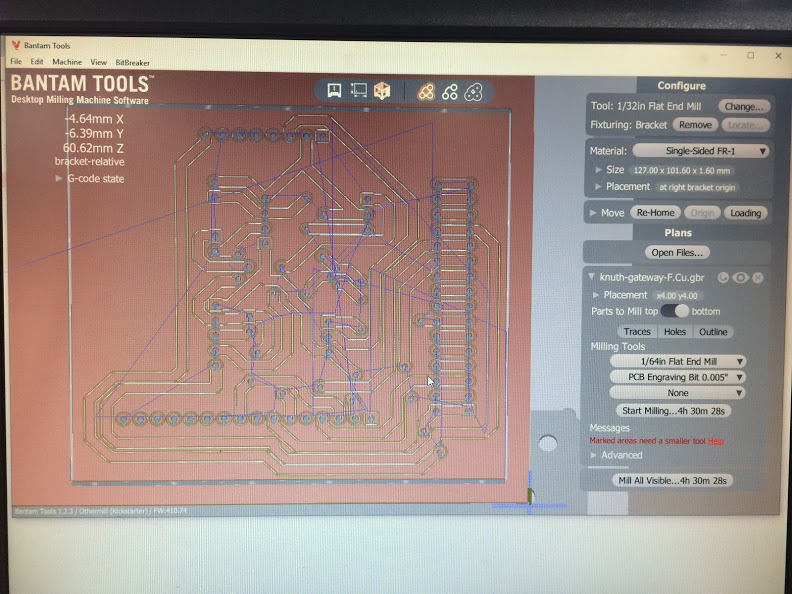
Gateway Board
I've also started working on the layout for the "Gateway Board" that will connect cellular modem, solar charger, power booster, and timer circuit together -- intended for a milled board at Artisan's:
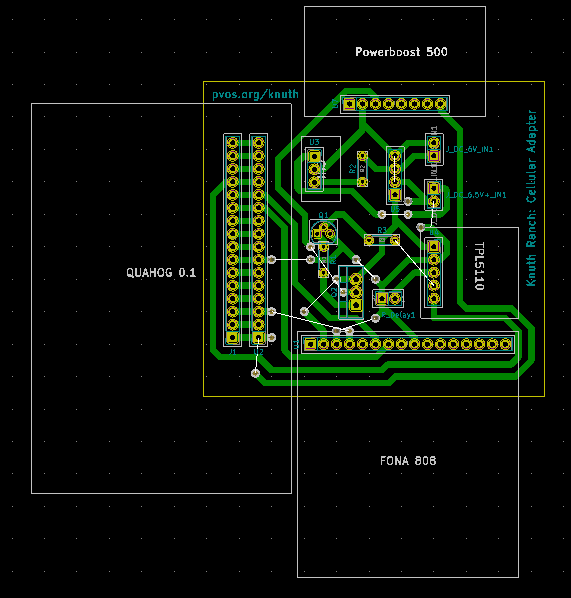
I'm trying something new -- rather than spend inordinate amounts of time trying to lay out a one-layer board, I'm using the standard technique of 'vias':
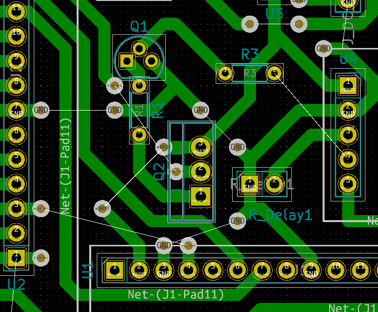
This will simply mean that I need to use my own 'jumper wires' between these vias (you can see them in the above layout diagram as white lines connecting vias). Should work out fine, as long as the OtherMill recognizes these vias.
Going to double check the schematic tonight, then plan to mill the board out tomorrow.
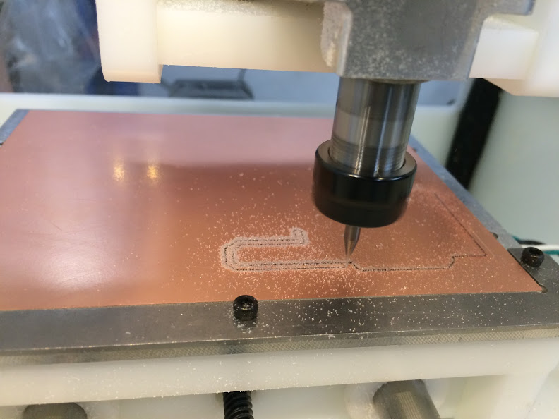
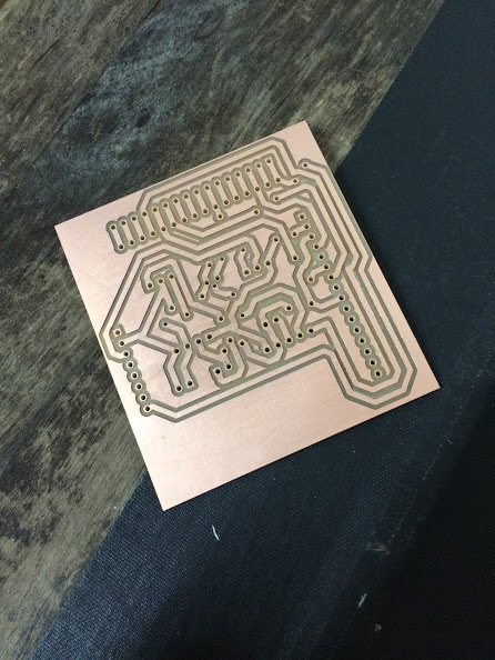
-- Update July 5, 2019 --
On Wednesday I milled out the boards. Made two small mistakes: the footprint on the powerboost included some extra pins; and the orientation on the FONA 808 module was flipped. But when I wired it up modulo these changes, it all works nicely!
On Monday I'll be able to redo the milled board -- and this time I might also design around the enclosure to make for a nice fit.
Todo:
- re-mill the board, with changes
- attempt to use the Decagon soil moisture sensors I've got, and figure out power for the Feather boards
- order a larger lithium ion battery
- order a higher-charging-rate Powerboost
- look into handheld soil moisture probes
-- Update Jul 21, 2019 --
Updates:
- Decagon 5TE soil moisture successfully connected and tested.
- Wasn't able to resurrect both; only have one to use. Will use for calibration.
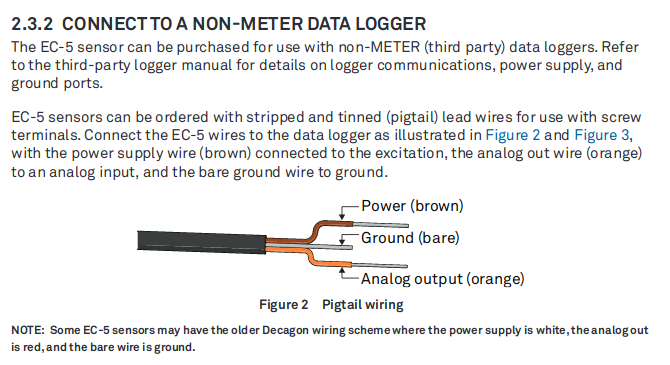
- Now trying to hook up EC-5 sensor
BOSSAC install for Circuitpython: https://learn.adafruit.com/welcome-to-circuitpython/non-uf2-installation
sudo ./bossac -p /dev/ttyACM1 -e -w -v -R --offset=0x2000 ./adafruit-circuitpython-feather_m0_rfm9x-en_US-4.0.2.bin
https://learn.adafruit.com/circuitpython-essentials/circuitpython-analog-in
import board
import time

from analogio import AnalogIn
analog_in = AnalogIn(board.A2)

while True:
    print(analog_in.value*3.3/65536)
    time.sleep(1)
Onewire code:
https://github.com/adafruit/Adafruit_CircuitPython_OneWire/releases