Edge Collective
UV Spectrophotometry
Designing a DIY UV SpectrophotometerQuick links
Background
Kearns et al have been working to develop lower-cost methods of testing that leverage a particular feature of biochar (and similar filters): some contaminants adbsorb much more easily than others. It turns out that the presence of one class of more weakly-adsorbed contaminants -- dissolved organic matter -- is relatively easy to assess with a lower-cost laboratory method: UV spectrophotometry.
The details of this approach are laid out in a 2020 article by Kearns et al:
- "Biochar Water Treatment for Control of Organic Micropollutants with UVA Surrogate Monitoring" -- https://www.liebertpub.com/doi/full/10.1089/ees.2020.0173 | PDF | local PDF
And specific instructions for performing the UV absorbance test are laid out in the supplementary section, here:
Further: while commercial UV spectrophotometers used in such tests are usually over $2000, there are several designs available for DIY forms of the instrument, costing under $100 in parts. We found one design to be particularly simple and well-characterized:
- "An accurate, precise, and affordable light emitting diode spectrophotometer for drinking water and other testing with limited resources" -- https://www.ncbi.nlm.nih.gov/pmc/articles/PMC6988917/
Our aim is to build a working prototype of this UV spectrophotometer, compare its performance to similar commercial instruments used in a laboratory, and then see if such an instrument might be easy to build and use in a community workshop setting.
Misc notes
-
Josh Kearns substack piece on Kearns et. al, "Leveraging DOM UV absorbance and fluorescence to accurately predict and monitor short-chain PFAS removal by fixed-bed carbon adsorbers"
-
Analog Devices article by L. Orozco, "Synchronous Detectors Facilitate Precision Low-Level Measurements"
Sun Mar 3 08:35:31 PM EST 2024
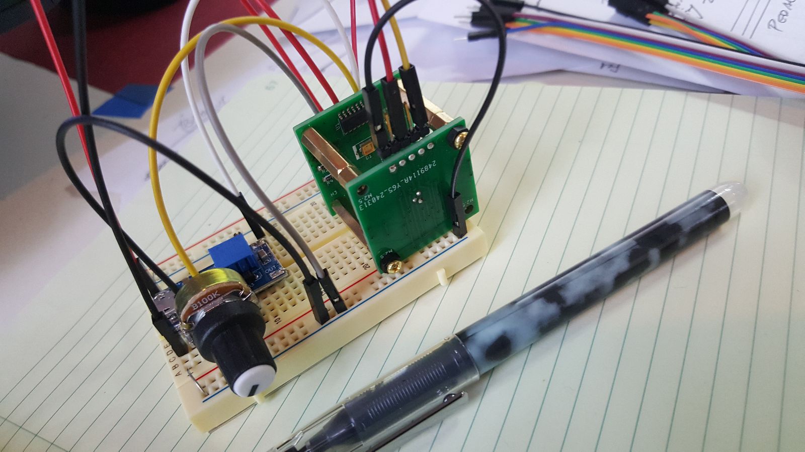
Building the circuit
Precision voltage to current converter
Adafruit 4-pin jumper cable here
Adafruit 4-pin jst ph stemma here
Adafruit JST 4-pin jst ph stemma SMD here
- diagram here
Mon Mar 11 05:20:16 PM EDT 2024
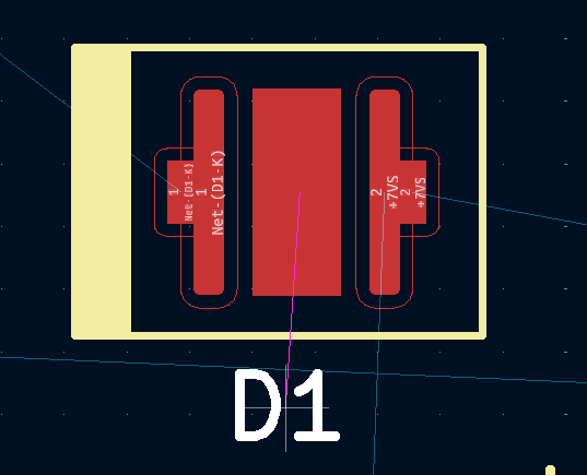
LED polarity 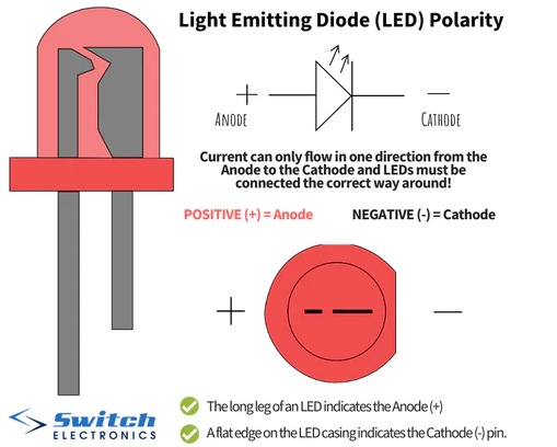
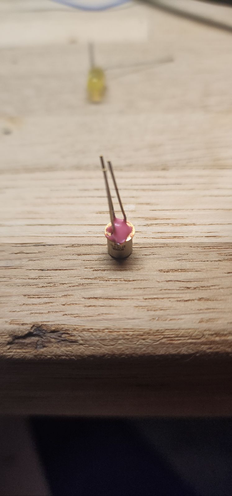
uv detector IN-C35PPCTGU0
datasheet here
custom footprint:
emitter v_0.1 ordered 3/11/24
detector v_0.1 ordered 3/12/24
Fri Mar 15 11:00:43 AM EDT 2024
instructrable on 555 as switch mode supply
Sat Mar 23 03:52:20 PM EDT 2024
Solder mask goof-up on UV emitter part!
Reference for UV emitter IN-C35PPCTGU0
Also: two pins on Q1 on emitter are 'flipped' -- need to fix pins -- was able to solder 'upside-down' anyway to fix
Mon Mar 25 08:17:39 PM EDT 2024
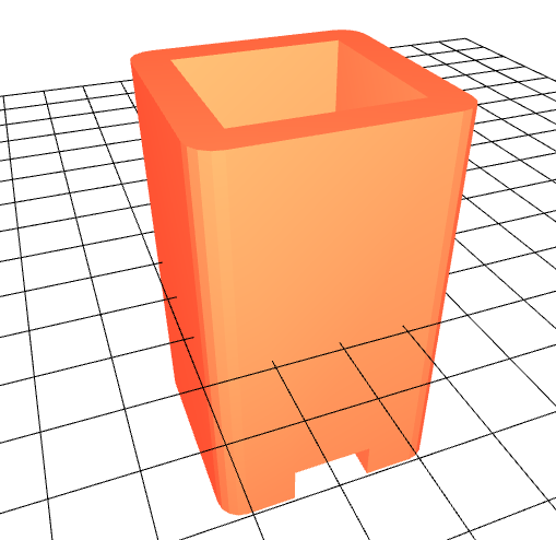
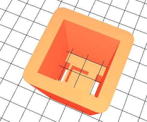
Made a quick 3d enclosure using openscad:
openscad and stl files are here
Fri Mar 29 08:57:08 PM EDT 2024
Water filtering, 1 micron
Selection at McMaster here
Nice pairing on Amazon:
Most recent prototype
Fri Apr 5 08:31:52 PM EDT 2024
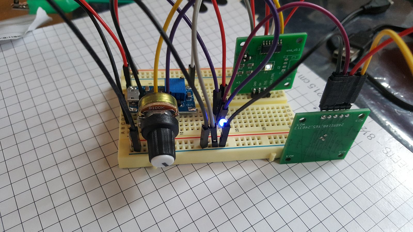
Working on detector v_0.2 ...
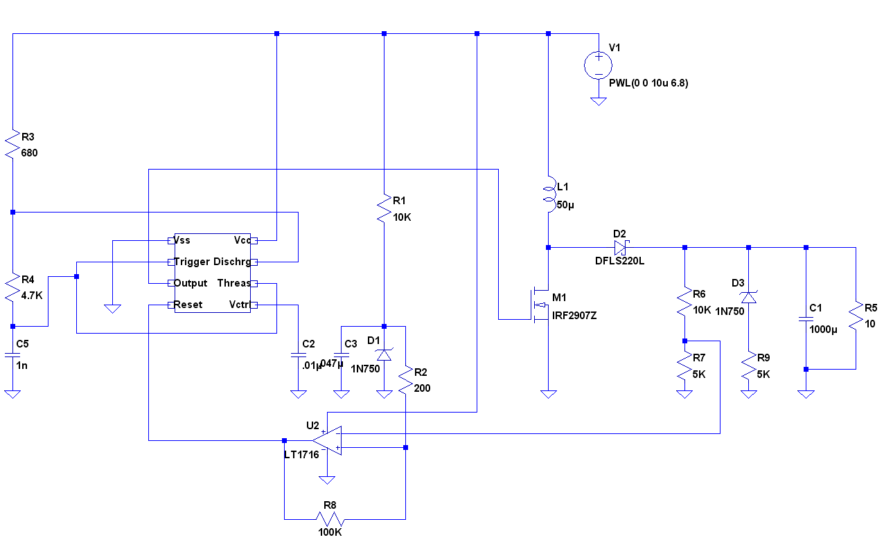
Sub-schematic that will be moved to a 'control board':
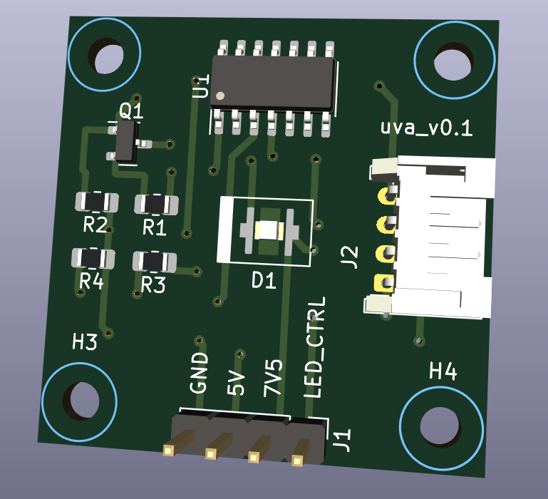
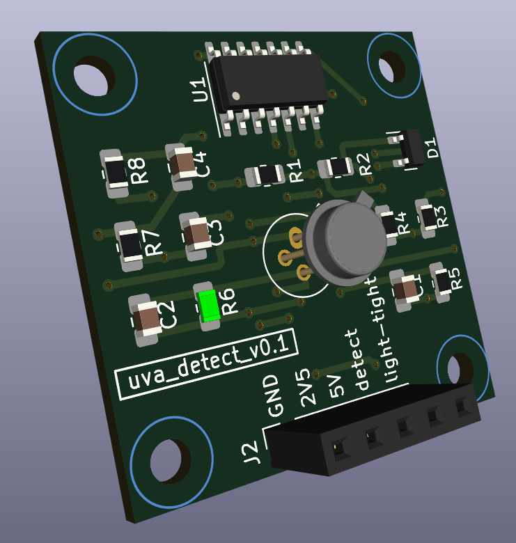
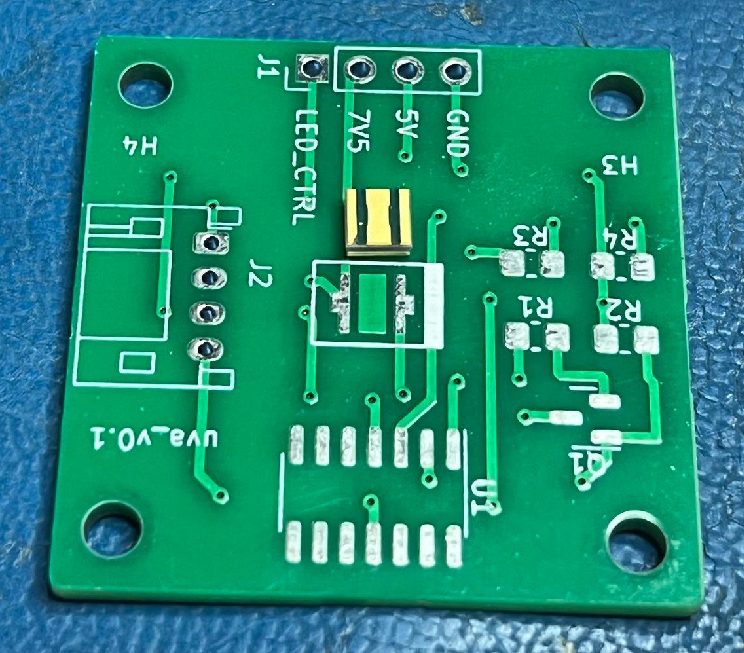
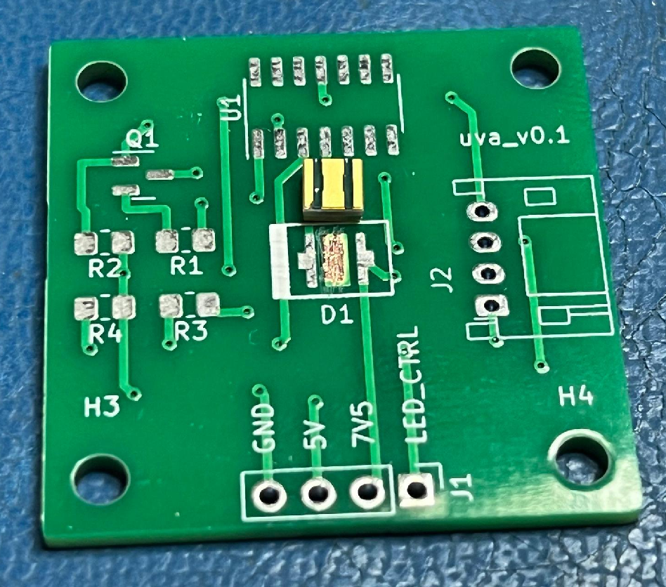
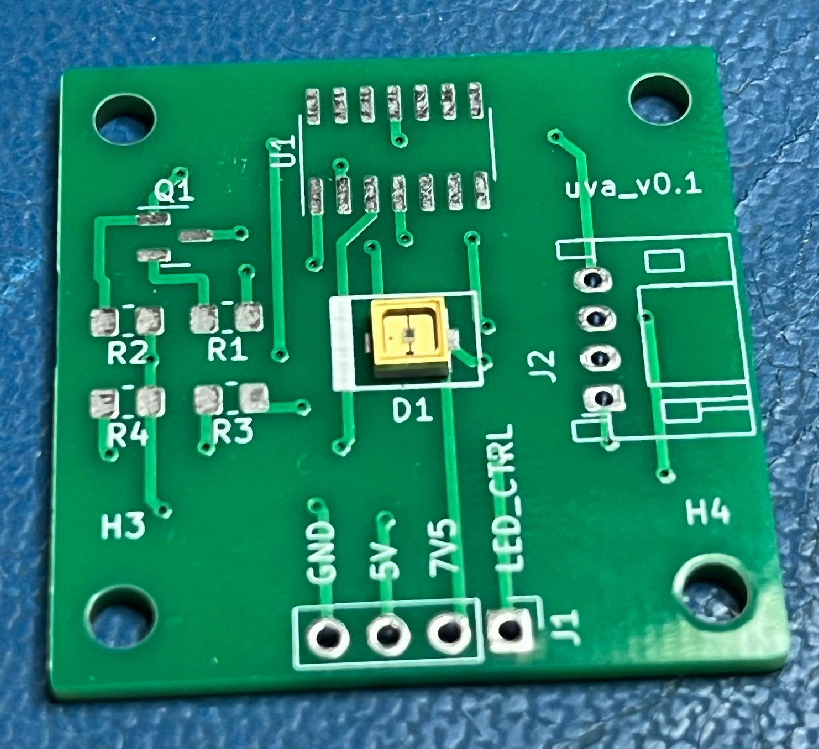
Version 0.1 footprint assignments:
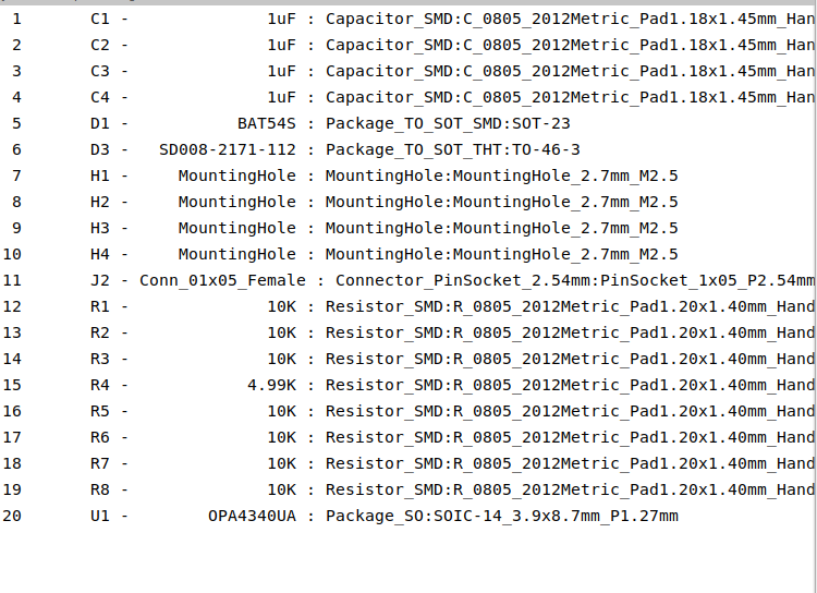
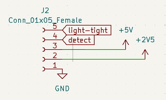
Version 0.1 pinout:
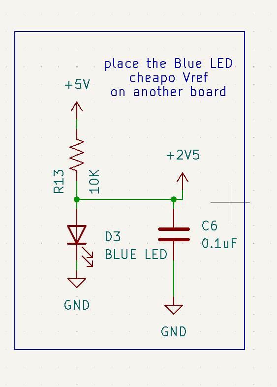
(need to add 2.5V ref)
Fri Apr 5 11:01:04 PM EDT 2024
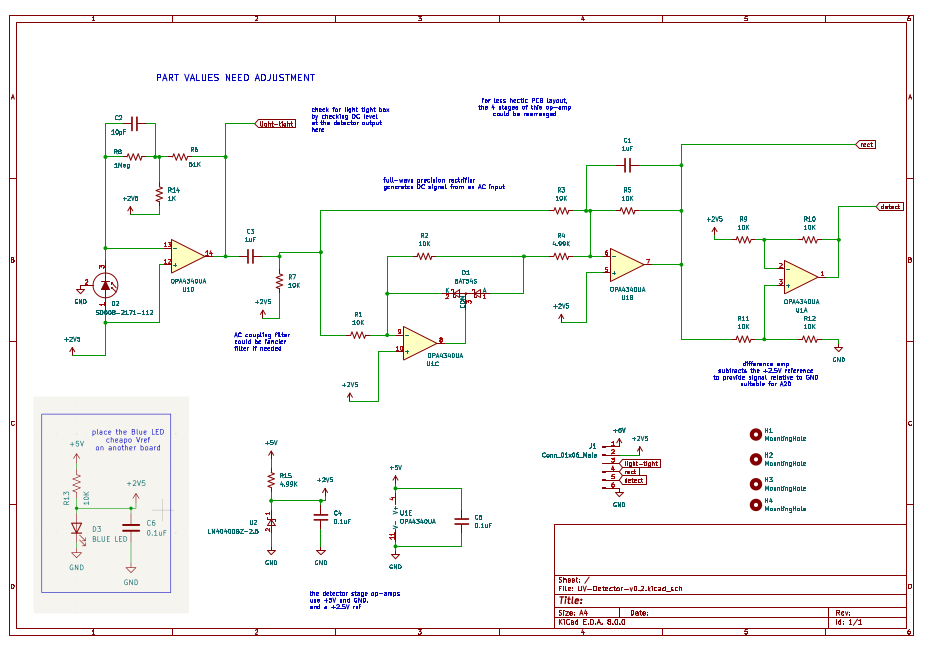
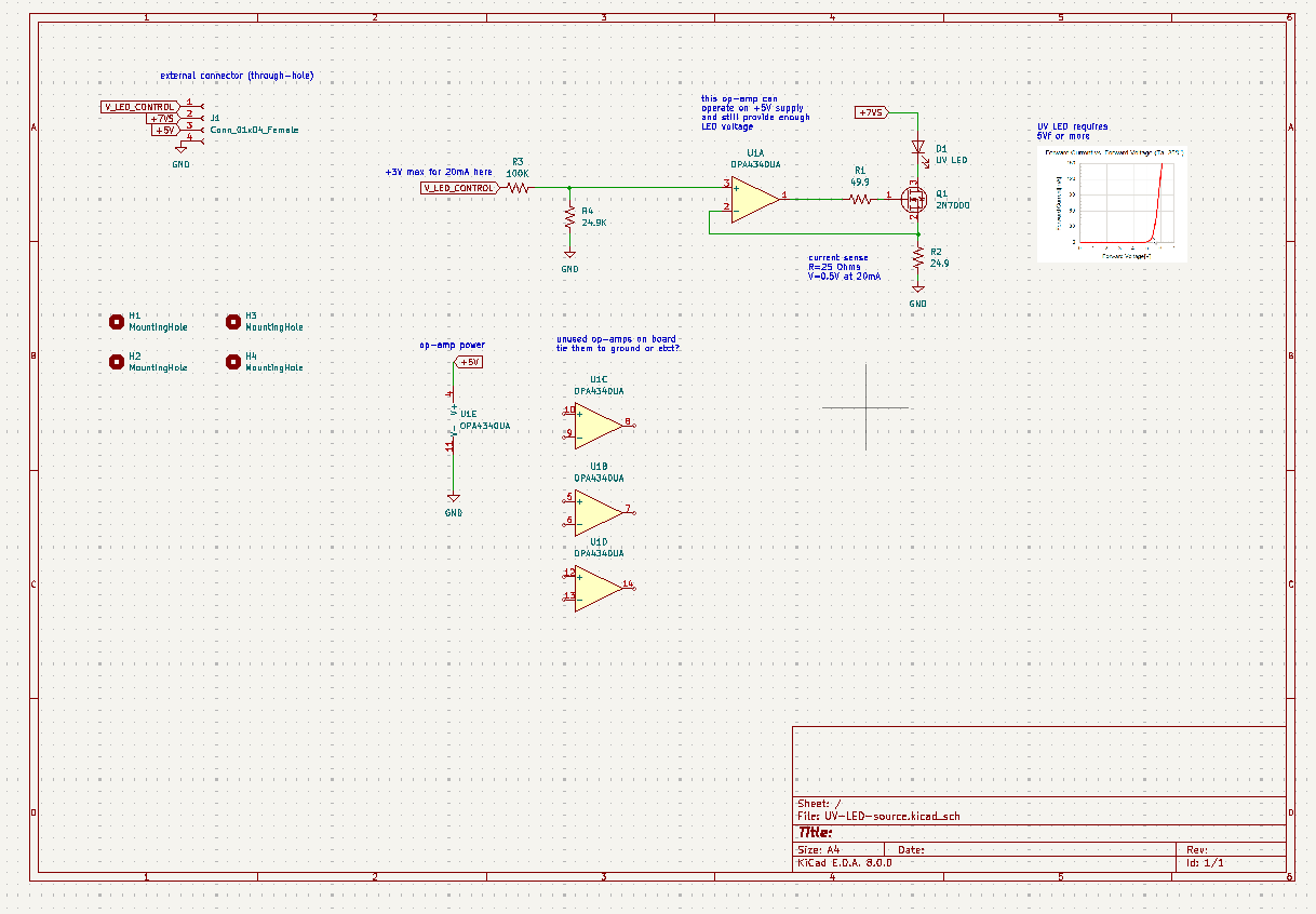
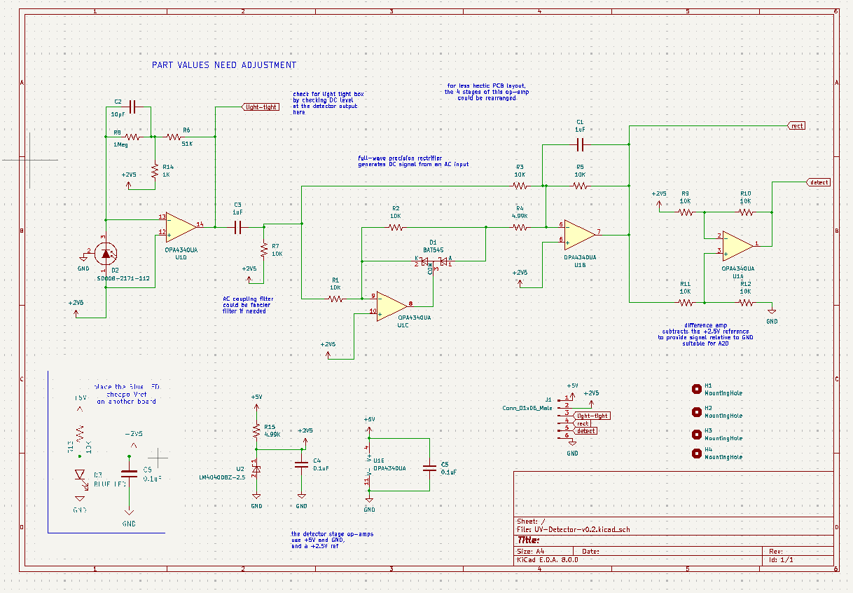
Detector schematic:
Emitter schematic:
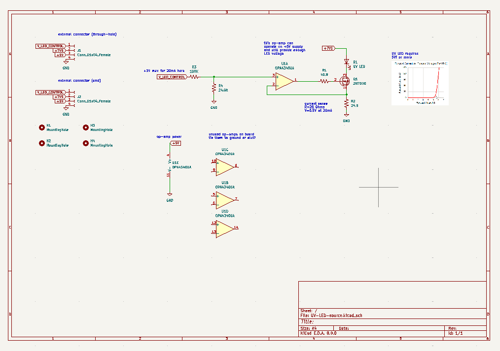
Revision 0.2 of emitter and detector
Sat Apr 6 10:25:06 PM EDT 2024
Edited footprint for LED (remove solder mask from center pad)
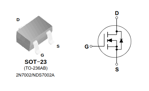
Revising mosfet pin assignment on emitter ...
2N7000 pinout:
emitter ver 0.2
Sat Apr 6 10:22:42 PM EDT 2024
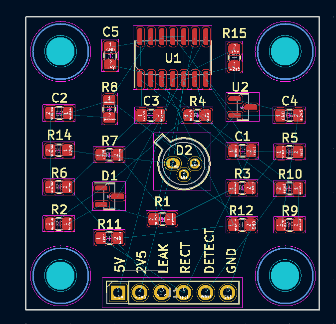
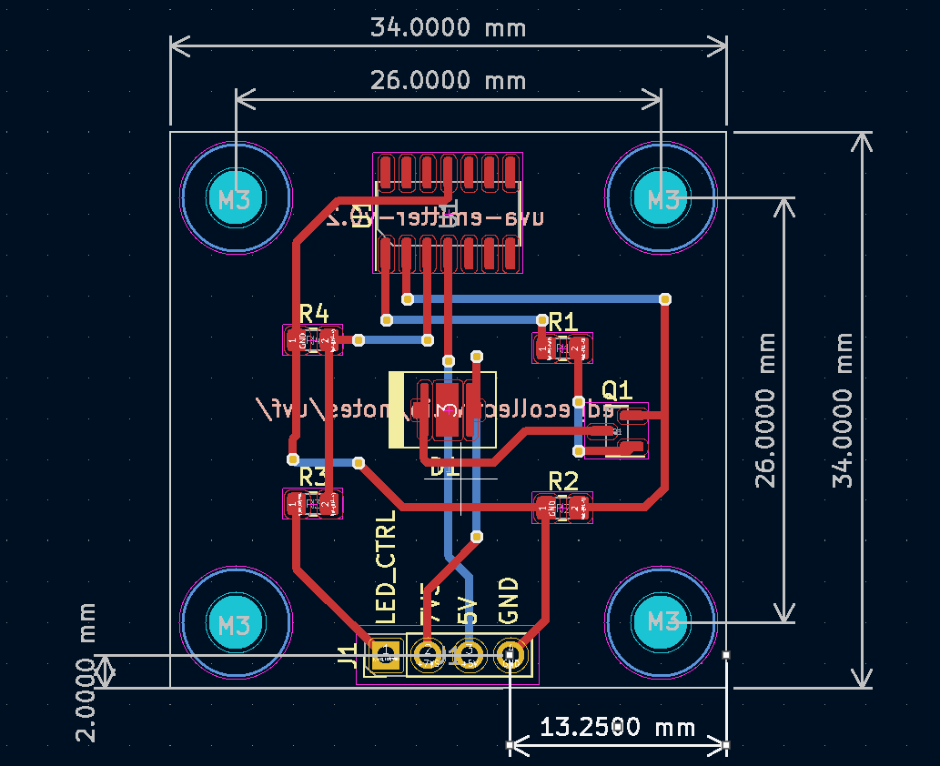
board layout:
schematic:
 )
)
board files:
detector ver 0.2
Sat Apr 6 10:22:55 PM EDT 2024
board layout:
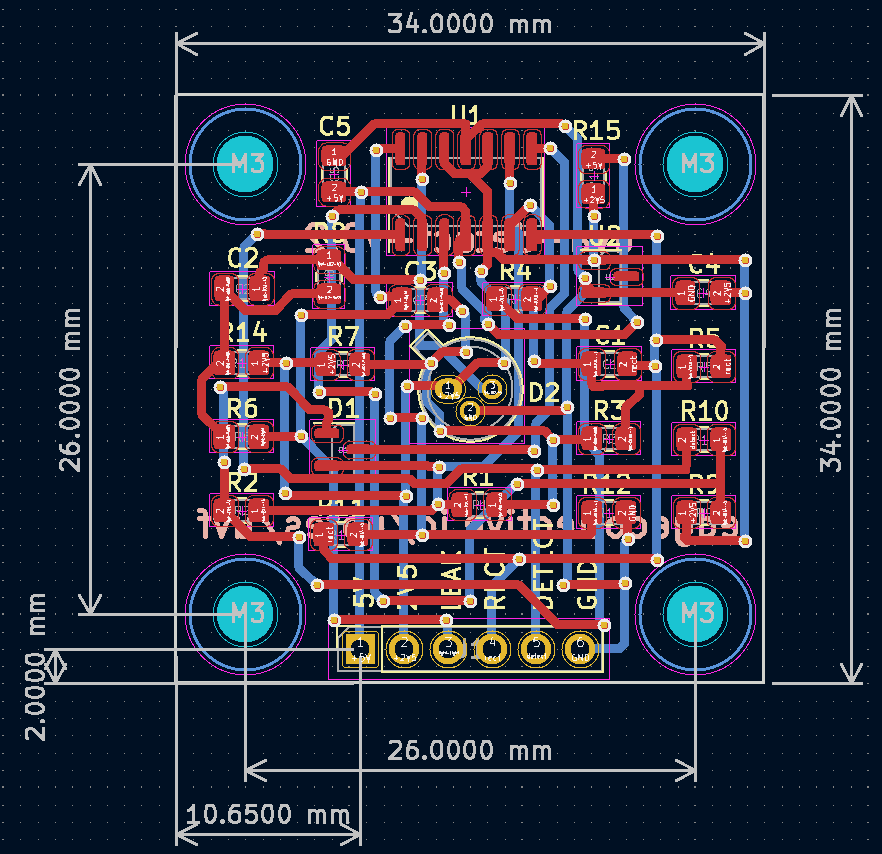
schematic:
 )
)
board files:
Mon Apr 15 08:18:11 PM EDT 2024
Collecting water samples and filtering through 1 um filter ...
3/4" NPT male + 3/4" barb fitting on Amazon
electric water transfer pump on Amazon
calibration of total organic carbon / uv254, EPA document pdf
'request a quote' for uva254 go here
might want to search for 'total organic carbon' (TOC)
An easy spectrophotometric acid-base titration protocol for dissolved organic matter
correlating uv254 to TOC, BOD, and COD video
Great paper on UV254 methods and applications. Note: correlations between uv254 and disinfection byproducts! references here
Mon Apr 29 09:29:59 PM EDT 2024
UV-Vis spec of Organic Compounds
UV-Vis spec, student resources
Nice general reference on uv-vis spec
Some UV-Vis chemistry examples
Sun May 5 02:54:23 PM EDT 2024
Notes on testing v0.2
idea: place all non-emitter/detector components on 'bottom' of board to allow easy access during testing
use voltage doubler on emitter board, as per this part here
replace the 5K R15 on detector board with R15 = 619 ohms
add current sense breakout above R2 on emitter board
add 555 boost and 555 emitter input on external feather board
add usb socket to motherboard for power
I was getting a measly 1.0V at the "2V5" reference pin - some buffoon (that is, me) seems to have chosen poorly the value of R15. I have replaced the 5K with a 619 Ohm resistor - and much better! I get 2.5Vreference.
And the signal at "leak" seems to act as I expected, in room light anyway. I still have to set up the LED and test a blank and wet cuvette ...
so, that T-network has a nice high gain!
And the input signal is 2.491 to 2.517 at 1kHz
Implies the equivalent feedback R is about 53.8Meg
There about 26nApp into the the stage with this test
So , 26mVpp into 1Meg for test current, and about 1.4Vpp output
Now to find what I did wrong at the LED stage ...
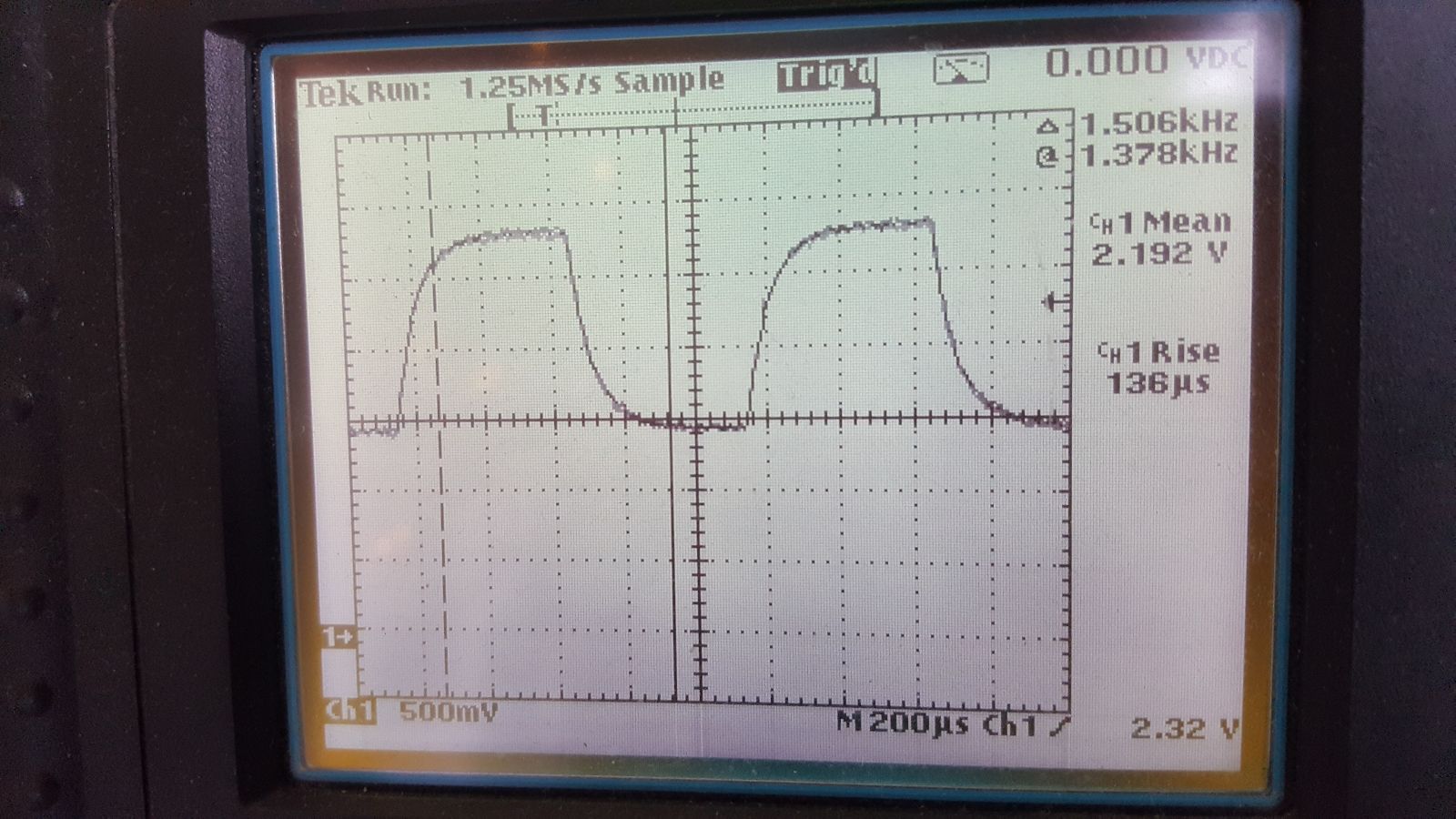
With 130us rise time that's about 2.7kHz tia bandwidth
Don't run the LED at 10kHz ..
OK I have a solid 0.5Vpp signal at "leak" node when I ping the LED board with 0V to 3V square wave at 500 Hz. On that emitter pcb I had to swap out R1 (was 49.9K) to 49.9 Ohms, and R2 (was 24.9K) to 24.9 Ohms. So, no cuvette, in the opto-mechanical system Craig designed, I see 0.5Vpp signal. Not bad.
less nice, I see some noise - I think that high gain TIA is also picking up 60Hz, and some other crap. more scope-ing to figure this out .... maybe we want a metal box ?