Edge Collective
Soil Monitoring System in Olathe, Colorado (USA)
Developing a Free and Open Source LoRa-based system (software, hardware); prototyping a remote node for capturing relaying data from an SDI-12 - based soil moisture sensor.Topics covered below:
- LSN50 Vegetronix temperature sensor setup
- Gateway setup
- Improving range
- LSN50 data capture
- LSN50 onewire
- Acclima relay node
March 22, 2020
Gateway Setup
Now that we have a field relay node design for capturing the soil moisture data and sending it to a LoRa gateway (based on the RAK / Raspberry Pi gateway), we are looking to optimize signal strength in the system.
Several resources are available online around this. I'll record them here later; but in particular, the tutorial I found particularly relevant was this one by Andreas Spiess: "What you always wanted to know about Antennas and nobody told you". Summary lessons from this video:
- Minimize the length of cable connecting the gateway to the external antenna. 10s of feet of cable connecting the gateway to an external antenna -- even high quality, low-loss cable -- can reduce the signal range significantly (in kilometers). Best to minimize this connection cable to the extent possible.
- With good line of sight, very long distances should be possible.
- The 'Fresnel effect' means that line of sight actually requires some margin above / below the direct line of sight.
- Always connect an antenna to the sender. Without an antenna, energy is reflected back into the sender, potentially damaging the electronics.
Antenna Options
The above leads me to think that our $50 Sparkfun LoRa Fiberglass Antenna, with its 5 dBi gain, is likely sufficient. I was able to achieve 5 miles line-of-sight communication between relay node and gateway using this antenna. The key variables to improve range seem to be: maximizing line-of-sight by increasing the height of the antenna, and using the shortest cable can to connect the gateway to the external antenna.
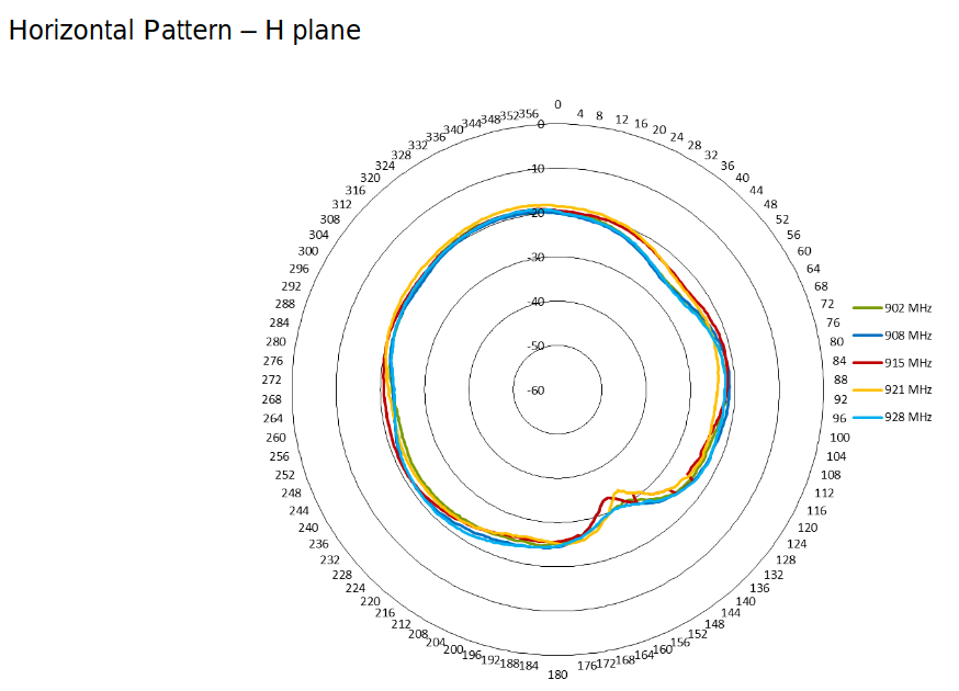
If, however, we wanted another 3dBi gain, we could Opt for the Taoglas OMB.915.B08F21, for $161. The datasheet indicates that it is still a fairly uniform / 'omni' antenna (which leads me to believe that our 5 dBi antenna, for which we don't have a datasheet, is likely even more uniform):
 |
|---|
| Signal amplification in the horizontal plane. |
Mounting the antenna
Nootropic Design has a nice short article describing their deployment of a RAK gateway outdoors. We can ignore the GPS antenna; this might be a cheap option for getting the fiberglass antenna mounted as high as possible.
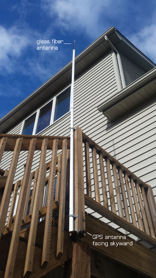 |
|---|
| Example outdoor antenna mounting. |
Cable options
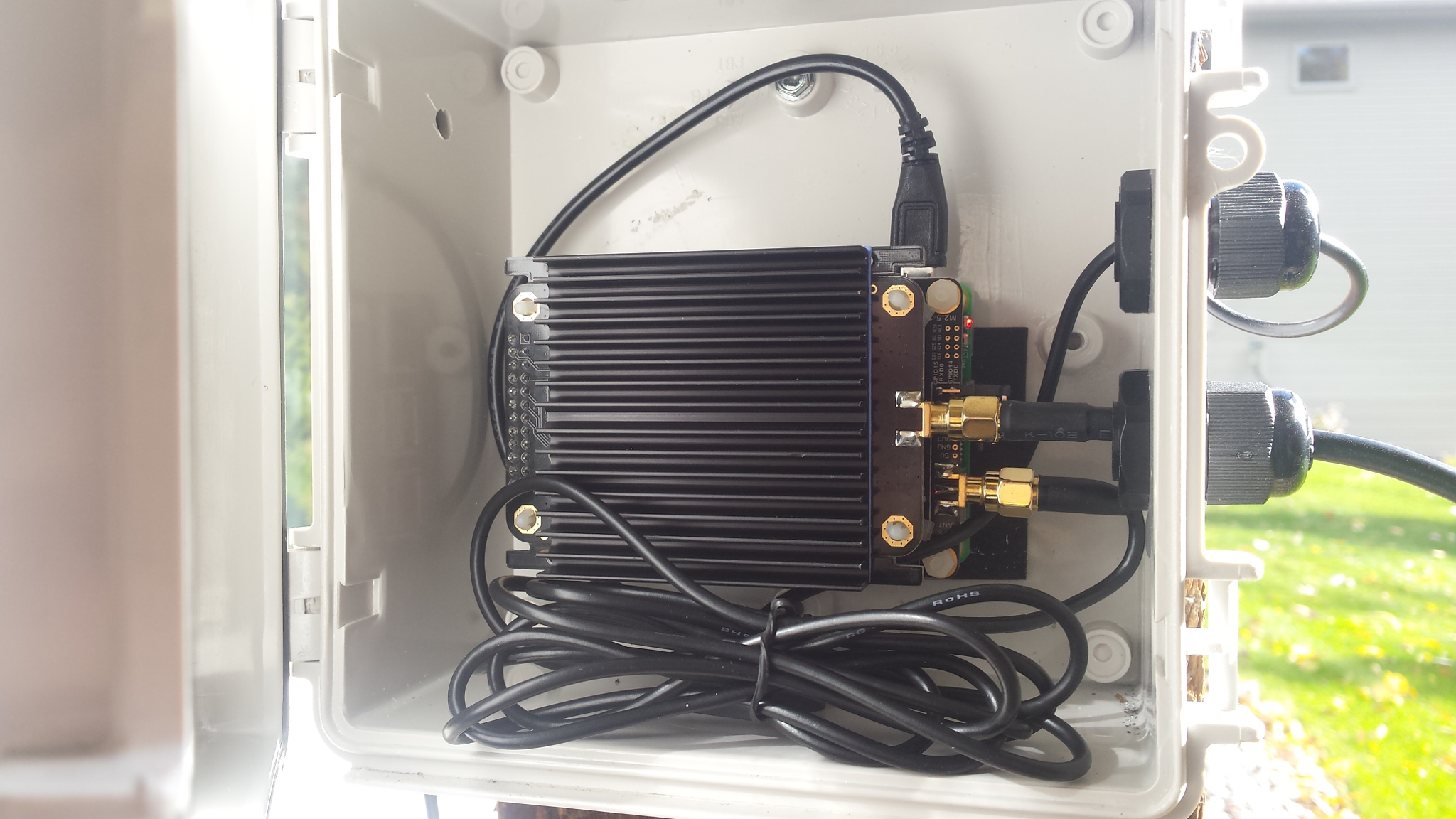
Despite the anticipated signal loss through the cable, it may be sufficiently difficult / inconvenient to place the gateway outdoors (lack of available wifi signal, wind / lightning / weather conditions), that it's worth using a low-loss cable to connect the gateway to the external antenna, and keep the gateway indoors.
If we need to use a long antenna extension cable, I've found some "Proxicast" Low-Loss Coax Extension Cable (50 Ohm) -- SmA Male to N Male, that seems to be a good option for low-loss cabling.
- 25 feet ($44) -- 2.1 dBi loss
- 36 feet ($67) -- 1.6 dBi loss (Note: are this and the previous figures swapped in the table above?)
- 50 feet ($86) -- 2.2 dBi loss
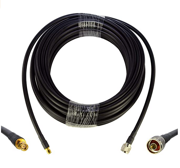 |
|---|
| Low-loss signal cable. |
The seller provides a chart with the "total signal loss" over the course of the cable:
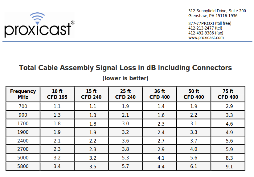 |
|---|
| Example of calculated values for signal loss in a particular cable. |
(Note: a general reference for signal loss per foot through various cable types at various frequences can be found here).
Patrick estimated about 40 feet of cable might be necessary: the chart indicates that the 50 foot cable option, at 900 MHz (our LoRa band), induces a loss of 2.2 dB.
I believe that this loss can simply be subtracted from whatever RSSI value we would have otherwise gotten with an 'ideal' (or very short) cable; and that it can also be subtracted from the gain of the antenna. Given that there are some LoRa base station antennas that are sold at 2 or 3 dBi, perhaps this loss is acceptable, so long as we try to maintain line of sight as best we can.
WiFi Extension Options
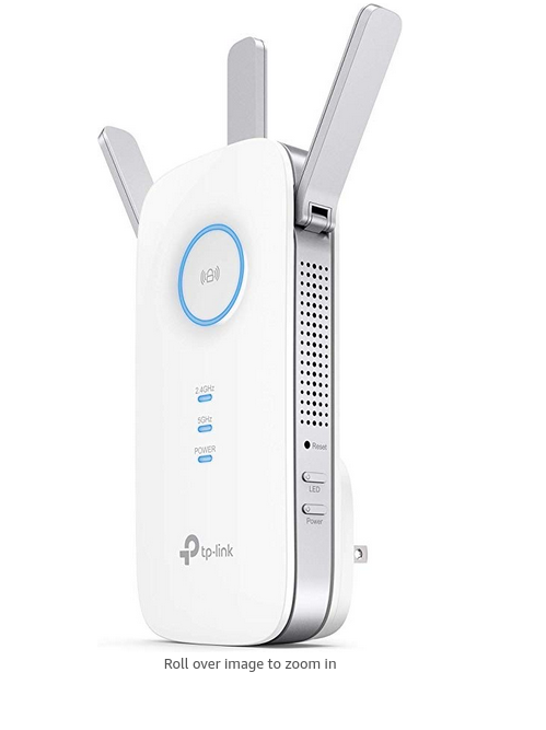 |
|---|
| TP-Link: an example of a Wifi Extender. |
Even if we use a cable, we will still need to connect the gateway to the wifi network, and this may require extending its range with a WiFi range extender.
Two options that seemed to be promising were:
- the NETGEAR WiFi Range Extender AC1200 for $35; it extends the range up to 1200 sq feet;
- the TP-Link AC1750 for $57; it extends the range up to 2000 sq feet.
External Gateway Enclosures
If we do opt to place the gateway outdoords, many options here could work for housing the gateway outdoors. If wind is a concern, a round PVC pipe might be a good option, as in this design from the Things network:
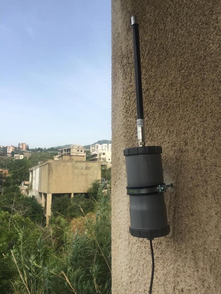 |
|---|
| An outdoor LoRa gateway. |
Otherwise, there are quite standard enclosures to be found online, with hinges, like this one used by Nootropic Design:
Overall Recommendations
- If it is possible to situate the external antenna within line of sight of the relay nodes, having a longer cable connector might not be so much of an issue. At the Olathe site, the antenna location on the roof may have line-of-sight to most of the fields.
- Therefore, the recommended purchase at this point will be both the cable and the wifi extender. The cable can be tried first; if it is of insufficient signal strength, then the wifi extender can be used to extend the wifi signal, and the gateway can be housed outdoors.
- For this reason an additional enclosure outside for the gateway may be a good purchase at this stage.
- Note that the Sigfox setup in Olathe may already be something we can leverage for the RAK gateway system, if the cable end matches, as it likely uses the same 900 Mhz ISM band, and the antenna is already nicely mounted on the roof.
March 28, 2020
LSN50 Vegetronix
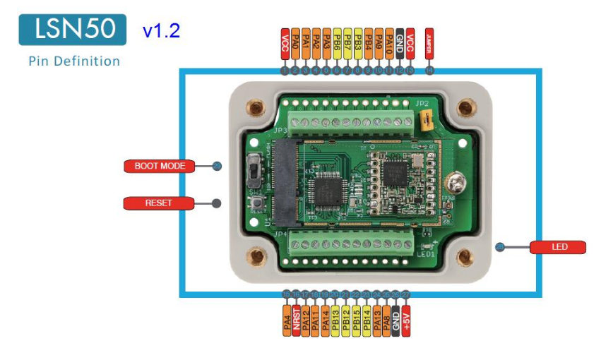 |
|---|
| The LSN50 version 1.2, with pins labeled. |
 |
|---|
| Pin functions of some typically-used pins on the LSN50. |
What worked with the CP2104:
- RXD --> P02
- TXD --> P03
- GND --> GND
Seems to take about 2 minutes to join network at start.
Command for changing interval (in units of milliseconds) to 60 seconds:
AT+TDC=60000
The Vegetronix VH400 provides temperature via analog output from 0.0 - 3.3V. Note: needs be powered with 3.5 - 20V. Wiring is as follows:
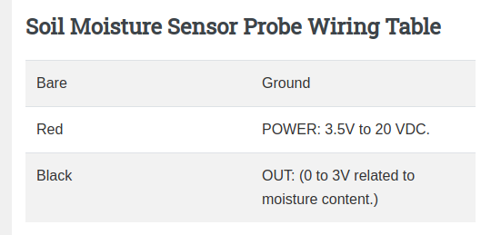 |
|---|
| Pin hookup for the Vegetronix soil temperature sensor (graphic shows 'soil moisture' but same applies to temeprature sensor). |
This means that to connect a VH400 to the LSN50, the wiring is as follows:
Vegetronix --> LSN50
- 'bare' -- GND
- 'red' -- 5V
- 'black' -- PA0
as per above LSN50 pinout / terminal diagram.
Burning a MicroSD card image of the RAK OS
This will require three steps:
-
Reformatting the microSD card. To do this on a MAC, you can follow this guide, which is demonstrated in this video.
-
Burning the RAK image to the formatted microSD card, using Balena Etcher. The image you'll want to download and burn is here.
30 March 2020
Improving Range
Recent range data collected by Patrick in Alamosa:
Overview of Fresnel Zones:
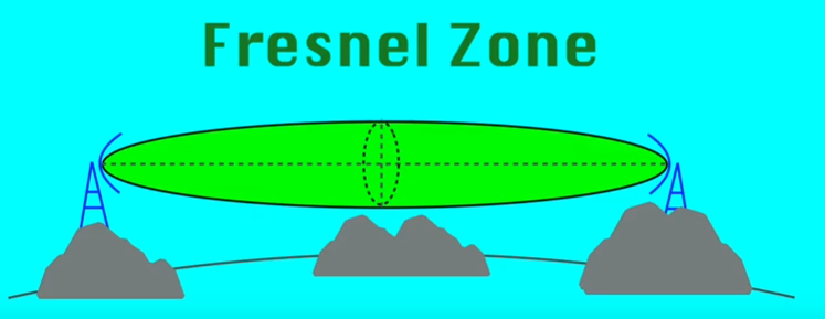 |
|---|
| The 'Fresnel Zone' for radio transmission close to the earth's surface. |
The Fresnel Zone. In order to achieve longer ranges and try to get good signal, there are two main issues to consider when placing the antenna:
- The first is the curvature of the earth -- this is relatively minor at short distances of course; but at a distance of 5 miles, you need the antenna to be at least 4 feet higher than the node to get line-of-sight -- assuming no other obstacles in between.
- The second is what's called the "Fresnel zone": you should try to maintain an ellipsoidal / football-shaped zone of clearance between the antenna and the node; or else a significant amount of the radio transmission that strikes surfaces inside that zone can bounce and self-interfere.
There's a nice post on calculating line-of-sight horizon and Fresnel zone, which provides the following equations:
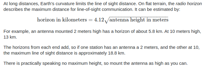 |
|---|
| Calculation of the Fresnel Zone geometry. |
Fresnel Zone Tutorial on Youtube by Mobile Fish
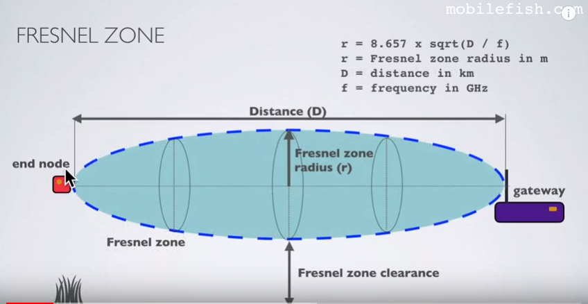
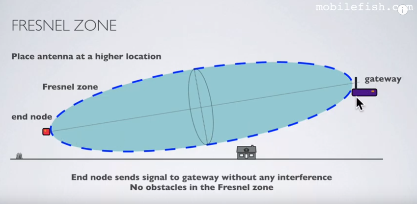
Note: at some point in above Youtube tutorial, they say that beyond 40% blockage, signal loss can be significant.
See final section of that video for doing calculation for curavature of earth + 60% fresnel zone:
Tutorial also covers the allowance in meters needed to accommodate the curvature of the earth:

See final section of that video for doing calculation for curavature of earth + 60% fresnel zone:
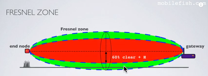
Our own Google Sheets calculator for 60% fresnel + earth curvature allowance:

Results:
- for 1 mile range, want about 30 feet of clearance at midpoint of ellipsoid;
- for 5 miles range, we want about 70 feet of clearance at midpoint of ellipsoid.
12 April 2020
LSN50 data capture
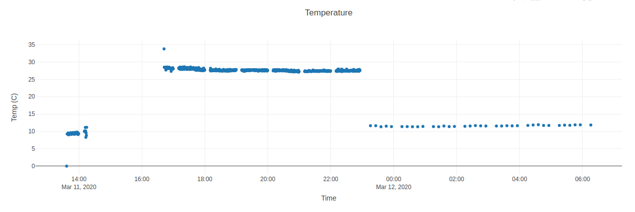
Got timestamps working properly with data in Plotly. Interesting that an initial experiment with the LSN50 seems to show some periodic 'gaps' in the data when broadcasting at 30 second intervals. Wonder if this is inherent to the LSN50, to the gateway, or to some other part of the system:
Drone Airspace Regulations
When using drones, important to check the local airspace rules. This map is really useful:
http://knowbeforeyoufly.org/air-space-map/
April 22, 2020
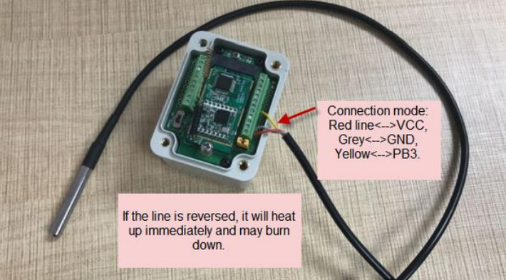
LSN50 and Onewire ds18b20

May 03, 2020
Notes on Acclima Relay Field Test and Deployment
Data graphs / links. Links to LSN50 and Acclima data (from Kelly and from Don) at olathe.edgecollective.io.
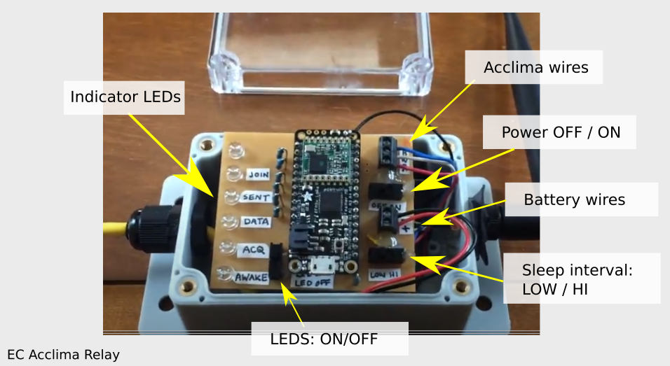
Field testing and deployment. Below is a procedure for 'field deployment' of the EC Acclima relay -- it's a way of testing the LoRa connection in the field quickly (short sleep interval, i.e. 'LOW') with visual feedback (LEDs on), making sure that things are working properly, then setting it up for long-term deployments (LEDs off to save power, sleep interval 'HIGH', typically one hour).
Procedure for Acclima field deployment
You can find a video demonstrating the below procedure, here.
- Switch the device power OFF
- Put the "LED ON" switch to "ON" so the indicator LEDs work (they should generally be switched to 'OFF' for long deployments on battery).
- Put the interval to "LOW" (30 sec)
- Turn the device power ON
- Watch the LEDs to make sure it gives you a JOIN and a SENT (explanation video here. Should JOIN within a minute or two, then should cycle through every 30 sec or so. You might wait for one or two cycles to make sure.
- Check here for new data. (you'll want to refresh the page) to see that you got new data values. It might take a minute. You might need to refresh the web page.
- Rejoice if you did see new values; curse if you didn't
- If you did -- then put the LEDs to OFF (to save battery), put the interval to HIGH (sleep interval to 1 hour instead of 30 sec), and replace the cover.
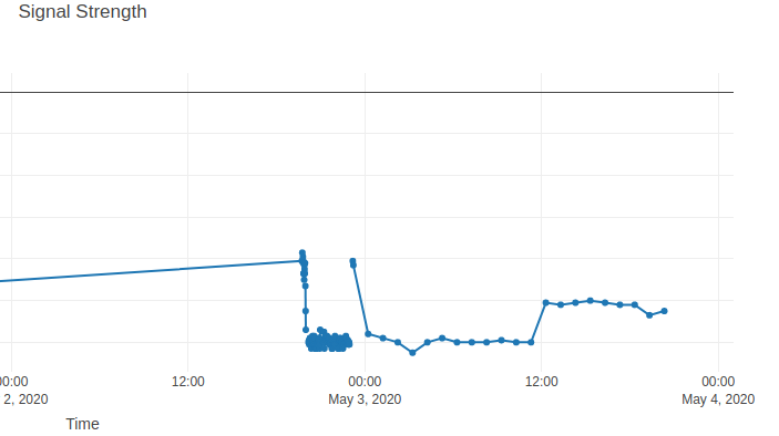
- If you didn't -- maybe it's out of range? (signal strength 'RSSI' below about 120); maybe it's low on batteries? Maybe the sensor wire is loose (it won't transmit if sensor wire is loose). Check those things and go back to step # 0 above ...
Testing the EC Acclima relay.
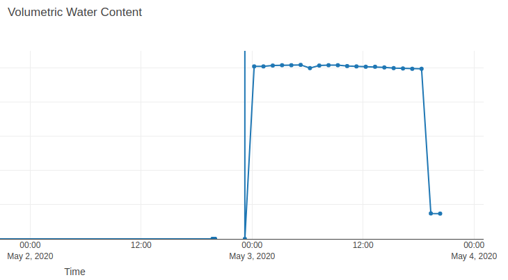
Witnessed odd behavior with the EC Acclima relay -- was not connecting. On power cycling, it connected, but sent odd data (values way out of bounds). [TO DO: POST PICS].
Then noticed that battery level was close to / just below recommended voltage for Acclima sensor.
Provisional diagnosis: the sensor was underpowered; this meant that originally it was causing the relay to fail to transmit to the gateway (the current firmware requires successful sensor data acquisition before transmit. TODO: rewrite so that it transmits 'error codes' (integers?)?).
Relay batteries were replaced, and now sensor is broadcasting regularly.
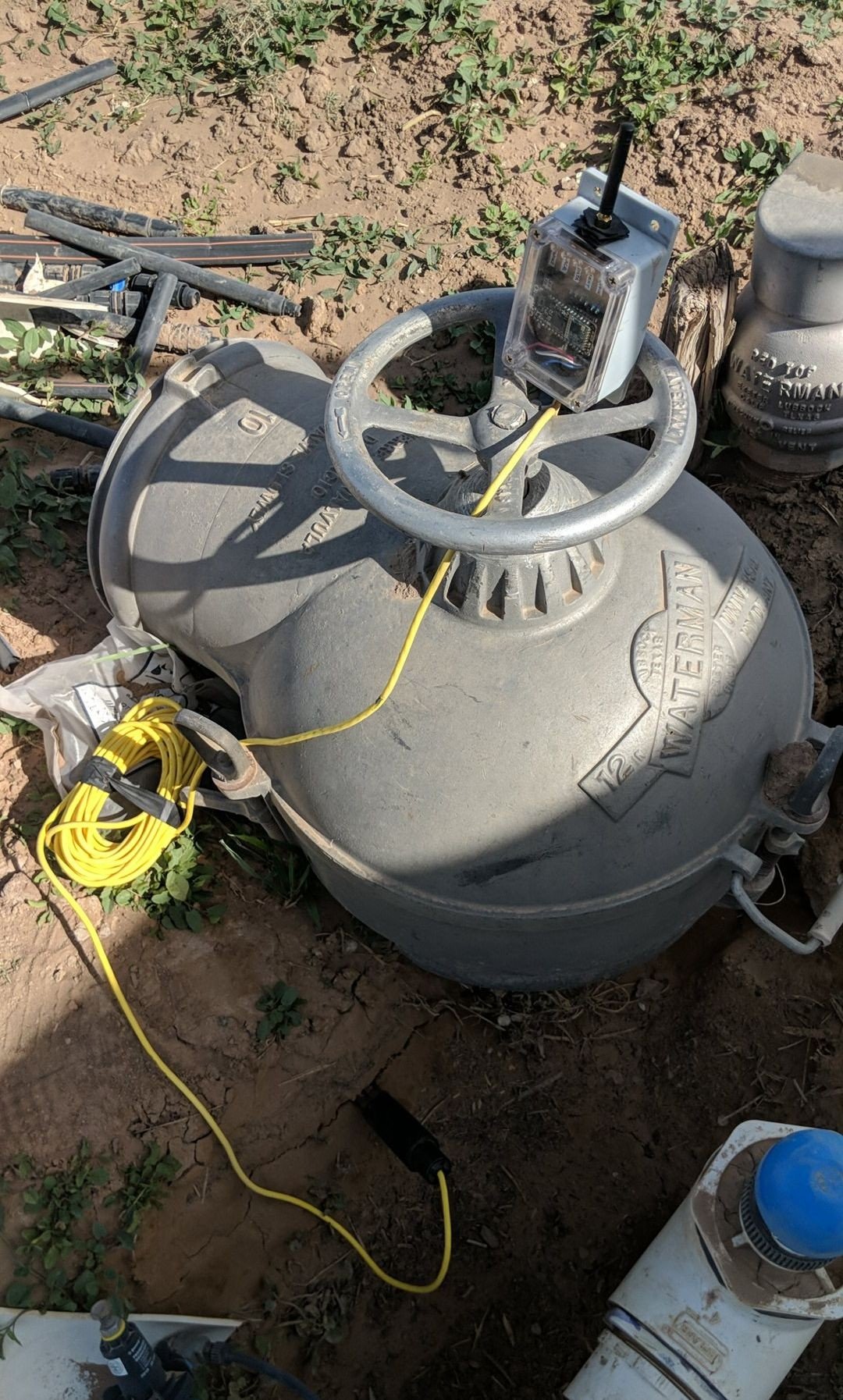
EC Acclima Relay was placed 3/4 mile from gateway. Prior, probe was placed directly in water (generating ~ %100 VWC readings). At new location, probe was placed in soil, which is generating readings of 14% VWC.
May 04, 2020
Periodically dropped data points?
All of the sensors currently deployed in Colorado seem to exhibit a similar behavior -- a periodic 'missing data point':


Merits investigation to see whether the issue is on the gateway (likely) or has to do with some periodic feature of the local internet connectivity.
Latest EC Acclima Relay Code
Note the Acclima relay code being used in CO currently is here. It uses the 'Cayenne' protocol in the OTAA mode. Also take care to note that this is in the 'sdi_failsafe' branch.
May 5, 2020
Update on 'periodically dropped data points' ...
The EC Acclima relay is back to broadcasting steadily, even though the LNS50 is still periodically hiccuping. The missing LSN50 data point is consistently around the top of the hour (there's one that would come through at about :02). Wondering if the reason that the EC relay is sometimes solidly ever hour-ish for a stretch, sometimes not, is that its timer is a little more than an hour (I set it for an hour, but the measurement / transmit process takes up to a minute). This would mean that the EC relay's 'phase' would to in and out of sync with a 'top of the hour' broadcast over time. I think in contrast the LSN50 firmware is quite nicely set up to hit relatively precise sleep increments, so that setting it for '10 minutes' means 10 minutes. Or, because it is broadcasting every 10 minutes, instead of every hour, it's more likely that we hit that gap?
To figure this out, there is some math to be done about the relative phases, and some numbers to check. But a quicker check might be to look into the Chirpstack / RAK gateway itself. Perhaps we can even set up a 'curl' to ping a remote site every minute via HTTP, and see if there it goes 'dark' once per hour ...

May 6, 2020
Hit snag with dhcpcd.conf file -- the version that RAK OS provides is intended, it seems, to provide a static IP address / WAP / etc when connected to eth0. Solution seems to be to comment out all of the last 5-ish lines in the /etc/dhcpcd.conf
TODO: remove the 'zoom' controls from the EC Acclima online display ...
(Update: was able to do this. But ultimately switched over to ChartsJS for now, see below).
May 11, 2020
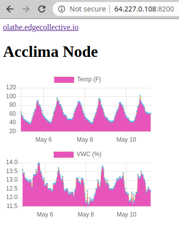
Couldn't quickly figure out odd dropped points bug when using Plotlyjs (should file a bug report?); switched over to Charts.js:
May 16, 2020
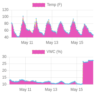
Acclima node now reading a higher VWC:
May 19, 2020
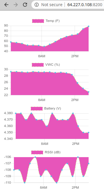
Added RSSI to new Acclima graph display; increased span of datapoints:
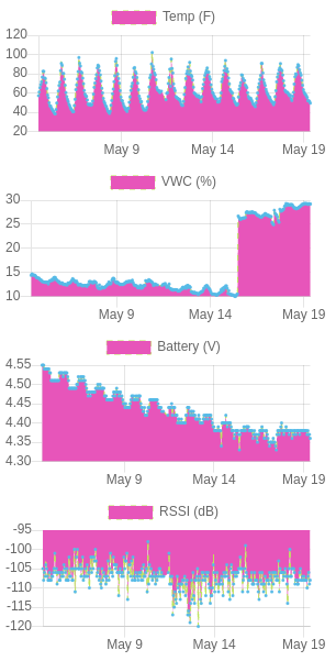
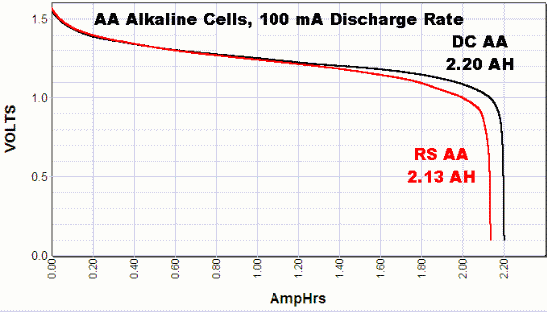
Note battery level -- we might last longer than original slope indicated, due to 's-shape' of AA-discharge curves ...
May 20, 2020
Testing another antenna on the remote node:
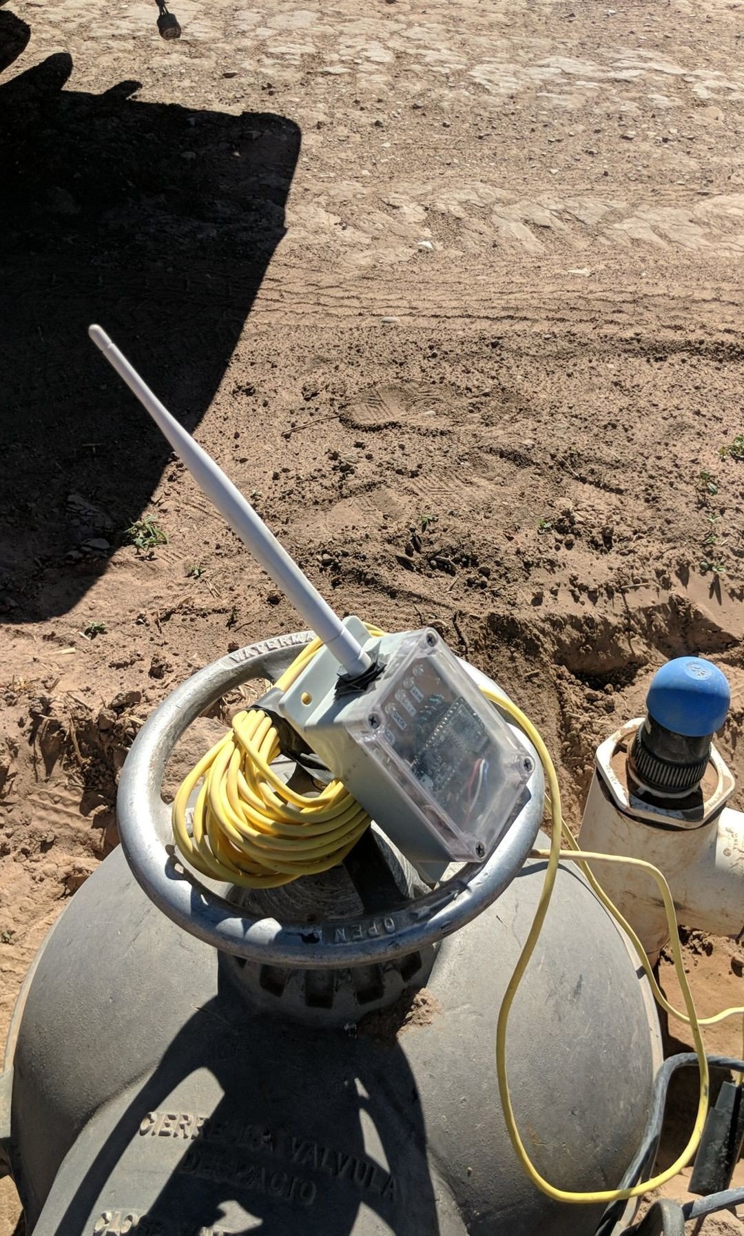 |
|---|
| Remote node experiment on David Harold's farm. |
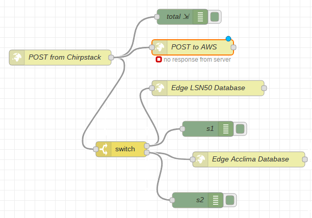
Checking to see whether David's Rak's NodeRed is piping data to Kelly's AWS NodeRed -- indeed it should be (ignore "no response from server" msg):
Looks like antenna switch resulted in signal drop. Also note that times on graph are in Mountain Time, not EST:
