Edge Collective
DIY Conductivity Sensor
Notes on development of DIY conductivity sensorsTemperature Measurement
RTD amp breakout from Adafruit.
Signal Sampling
Burr Brown App Note on precision absolute value circuits.
Signal generation
Prior Art Among Us
Don's last version in January, based off Craig's 4pstat is here
Craig's latest 4pstat is here
Don's simplified 4 probe based on an earlier design is here
Craig comments
What I found that seems to work well on the driven shield lines was to use some RC snubbers to ground after the 50 Ohm output resistor. Values like 10 Ohm and 100nF give you a corner frequency of 160kHz - if your bandwidth is 10kHz that should likely work out.
Don, if you use my design, there are lots of mods needed to stop it from oscillating.
If you are doing a virtual ground, I suggest using the in-the-loop compensation circuit I got from AoE3
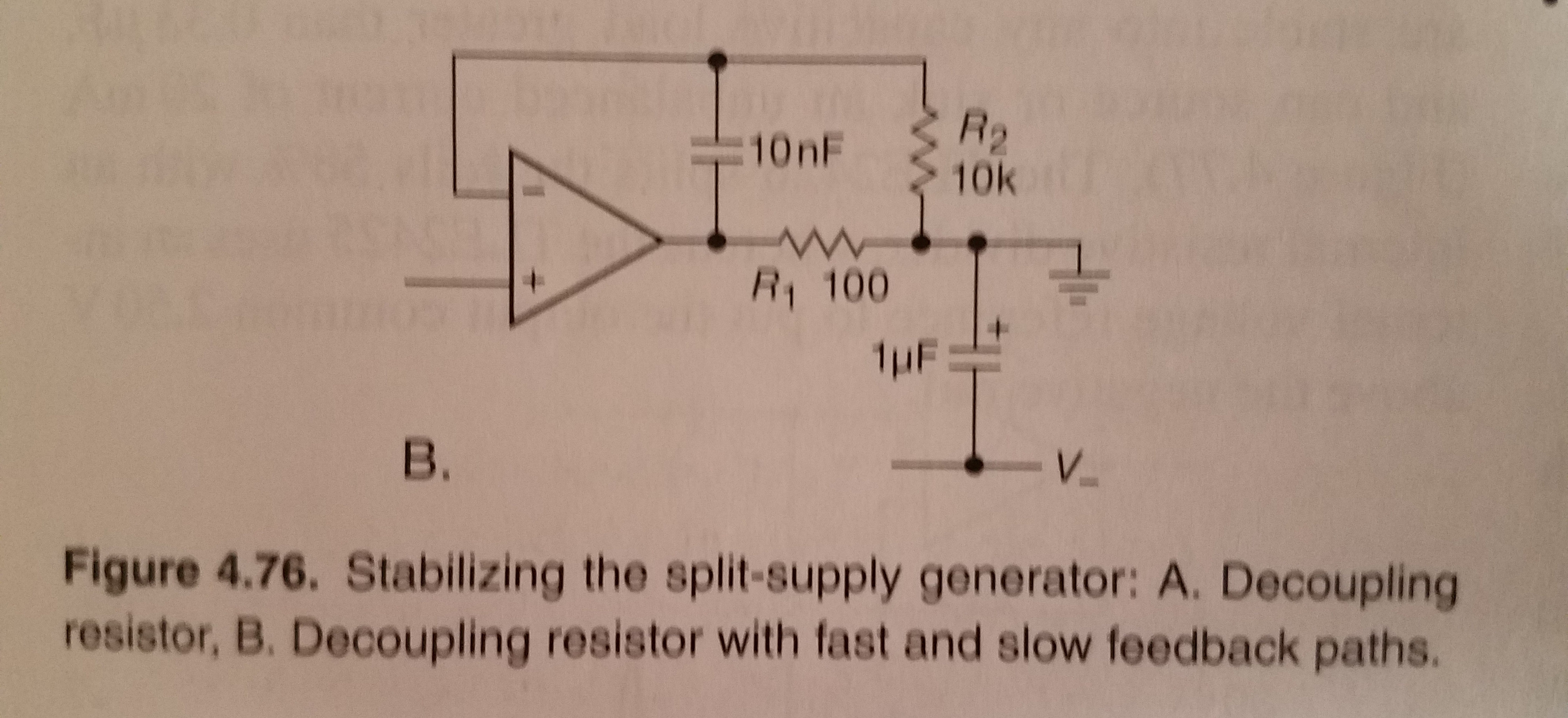 |
|---|
| In-the-loop compensation scheme suggested by Craig here. |
Actually I wonder if the corner frequency is actually 6X lower because of the added 50 Ohm resistor? If that is the case, it might be better to back off the capacitance a bit And what about output resistance from the opamp (Mike, I'm looking at you)? If that's like around 100 Ohm maybe we'd be smart using an even smaller cap. This could be why I did not make my intended bandwidth of 100kHz on the bodged up 4pstat.
Revision Notes
As of 10-02-2020:
- use an OPA281 for the TIA (current measurement)
- use an INA2331 for the INAMP (voltage measurement)
- add the driven shield, snubs, and in-the-loop compensation as per Craig's design & mods
- use through-hole headers for any passives we might want to swap (avoiding the MUX chip for now) to simplify the board
Don's current attempt at the above is here.
As of 10-06-2020:
- Made suggested modifications by C.V. & M.B.. Resultant schematic is version 0.4.
As of 10-07-2020:
- Mike: 'Do you want a power supply decoupling cap on the current sense TIA, U3?'
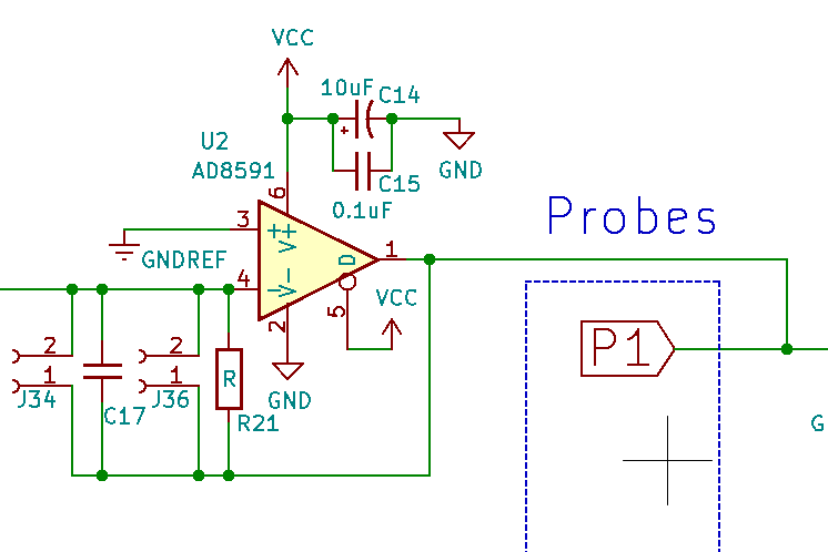
- Craig: 'What's driving P1 in this circuit? Shouldn't we have some amp here?'
'Adder inputs' section of Craig's 4PSTAT schematic:
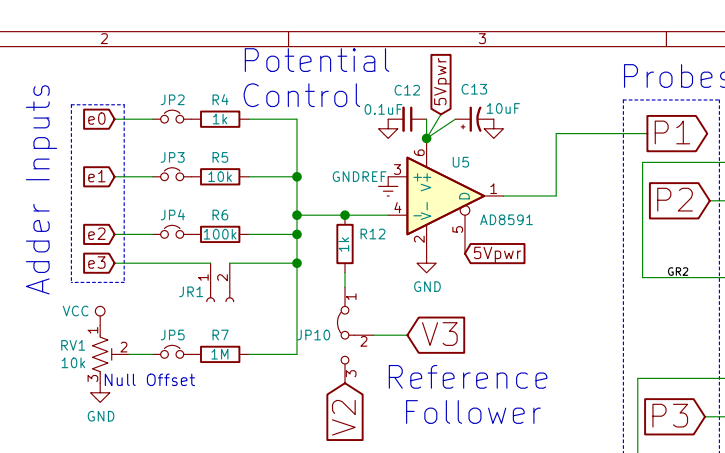 |
|---|
| From Craig's schematic here. |
As of Oct 9 2020:
 |
|---|
| Revision A of the 0.4 EC-4P circuit: attempt at a simpler 'conductivity' measurement with adder amp feedback coming directly from the the amp output. See discussion here. |
Adder circuit explanation on wikipedia.
Oops. Above places C16 incorrectly:
Craig:
It looks like you are shorting out C16. Instead C16 should go across R21 to the summing junction.
Think of it this way, your gain at DC for each adder pathway (e0-e3) should be R21/Rn. What the feedback capacitor C16 does is to short out R21 for high frequency signals where its impedance is small; thus it rolls off the gain at high frequencies, the corner frequency being 1/(2piR21*C16). Just set that, say 5X, above your highest intended signal frequency and you will have smoothed DAC signals and more stability.
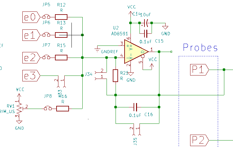
Correction:
 |
|---|
| Revision B of the 0.4 EC-4P circuit: attempt at a simpler 'conductivity' measurement with adder amp feedback coming directly from the the amp output. See discussion here. |
References / Datasheets
Useful misc info
via Stackoverflow: Command to get latest URL for remote commit:
git ls-remote git://github.com/<user>/<project>.git
2020 NOV 12
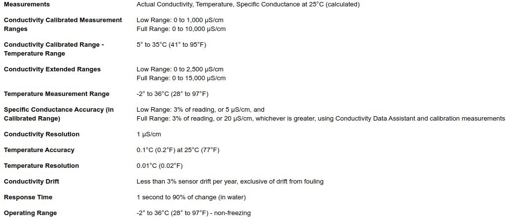
HOBO Freshwater datalogger product page here.