Radiohead LoRa Mesh Field Test
Test of Radiohead mesh networking functionality.
We used some Arduino-based devices to demonstrate the mesh functionality of the Radiohead library, a common radio library for LoRa radio devices.
Our starting point was the code from a nootropic design blog post. Our version adds GPS funcitonality, using some inexpensive GPS modules and some Adafruit Feather LoRa boards.
Trial data
In our first trial, we deployed three nodes at a residence in Lincoln, MA USA, as depicted in Fig 1 below. Node #1 (blue) is stationary, and connected to a laptop which is recording any data received by Node #1 (via a Python script). Nodes #2 (red) and #3 (green) are mobile, and equipped with GPS; every few seconds they make a GPS measurement, and attempt to send their latitude and longitude back to Node #1.
 |
| Fig 1: Snapshot from an animated depiction of our first mesh networking test. The blue dot is Node #1 (stationary); Nodes #2 (green) and #3 (red) both attempt to send their GPS coordinates back to Node #1 every few seconds. In this snapshot we see a situation where Node #2 traveled too far from Node #1 to reach it directly, and needed to relay its data via Node #2. |
What you can see in the animation of the trial data is the following:
- During the first part of the journey, Nodes #2 and #3 are able to send their data directly back to Node #1, as they are easily within range.
- At some point, we found that lost the connection to Node #1 due to topography / obstructions; so we backtracked a bit to where we still had a good signal, and dropped off Node #3 by the side of the road.
- We then continued to walk down the path with Node #2.
- At various points, Node #2 loses its connection to Node #1, and re-routes (according to the Radiohead mesh algorithm) its messages via Node #3.
You can also observe that at some point in our journey -- with Node #2, walking away from Node #1 -- we regain our connection to Node #1 (likely because we went up a hill, and regained line-of-sight). We believe that the Radiohead algorithm will simply stick with whatever route was most recently successful until it fails; so perhaps this means that when we see Node #2 and Node #3 connecting, the connection between Node #2 and Node #3 must have dropped, prior. will look into this.
Trial Pics
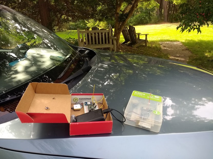 |
| Node 2 (left) and Node 3 (right) before the field test. |
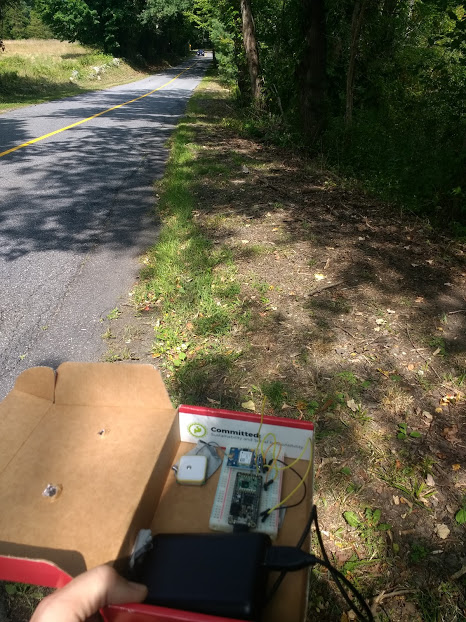 |
| Node 2 -- the 'red' node in the animation above -- that traveled the furthest distance away from Node 1. |
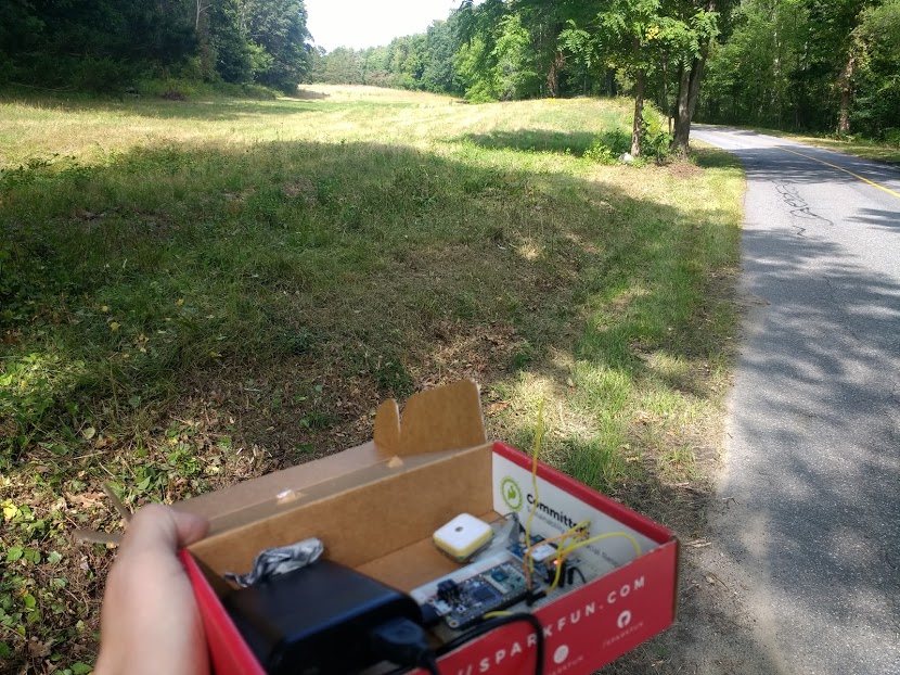 |
| Node 2 on the road ... |
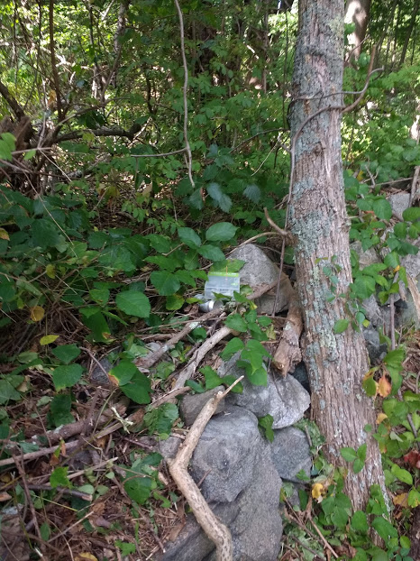 |
| Node 3, placed in on a stone wall to serve as a 'relay node' between Node 1 and Node 2. |
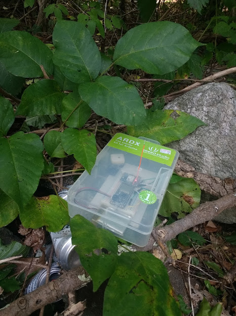 |
| Closeup of Node 3. |


