Edge Collective
Lower-power, resilient operation
Learning to use the 'sleep' mode of the satellite modem; sleeping the microcontroller and depth sensor using a TPL5110 timer chip.Video Updates
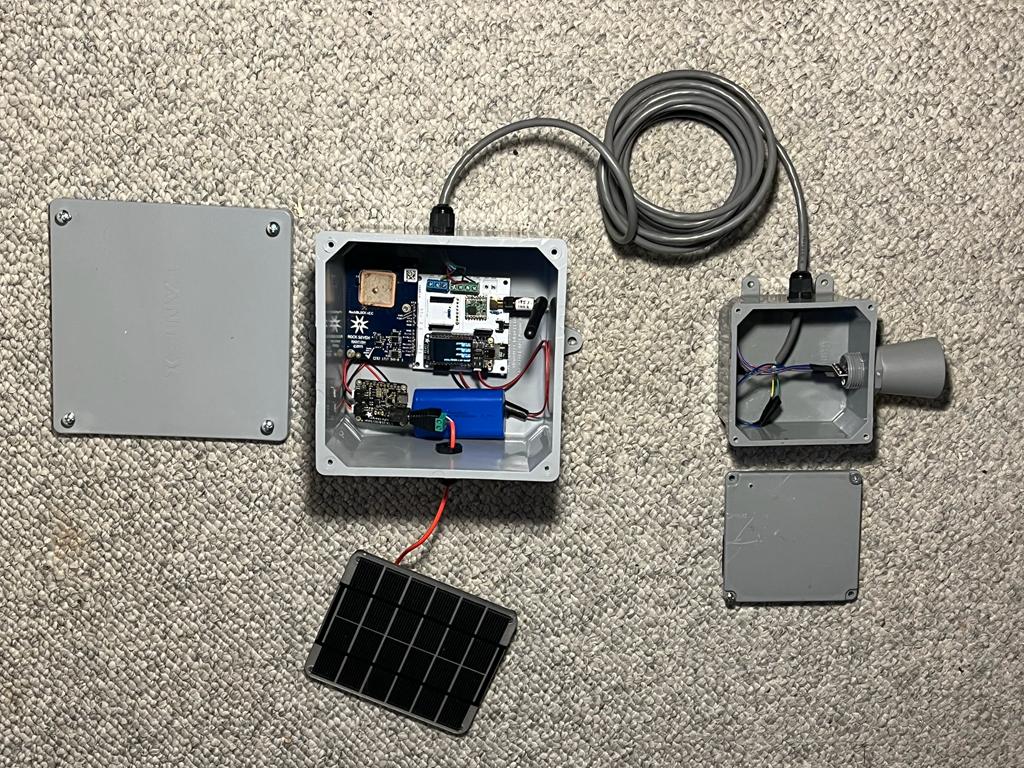
Prototype #1
Power testing
sat modem "disabled" + esp32-s2 tft asleep -- 3.68 mA sat modem "enabled" + esp32-s2 tft asleep -- 3.66 mA
essentially no difference.
Seems like the esp32-s2 with no display sleeps at about .7 mA
Apparent issue with the watchdog timer: https://github.com/adafruit/circuitpython/issues/5890
Testing out LoRa - based depth:
http://bayou.pvos.org/data/pb87ap97vgrr
Running every 2 seconds as a test ... latest version is sweet-p/firmware/board_ver_0.2/v4.0
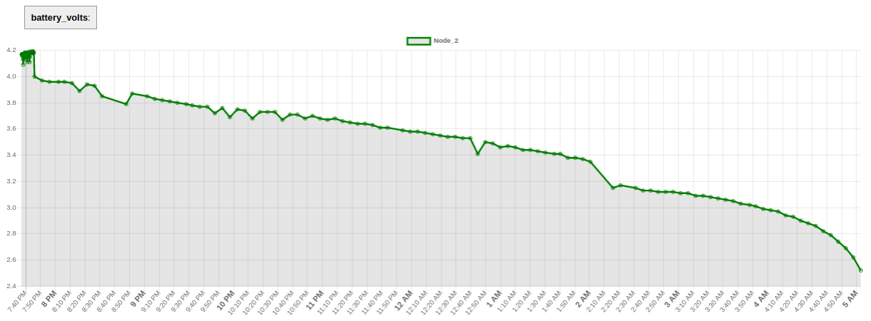
Experiment overnight, May 30th:
http://bayou.pvos.org/data/pb87ap97vgrr?plot_param=battery_volts
Power consumption guidance for the sat modem:
https://docs.rockblock.rock7.com/docs/power-consumption-guidance
Very strange behavior when pull down the satellite 'on/off pin'. I've added an external resistor pull-down to make sure it stays down. Seems like the voltage is still around 1.5V, nevertheless. Stronger pulldown required?
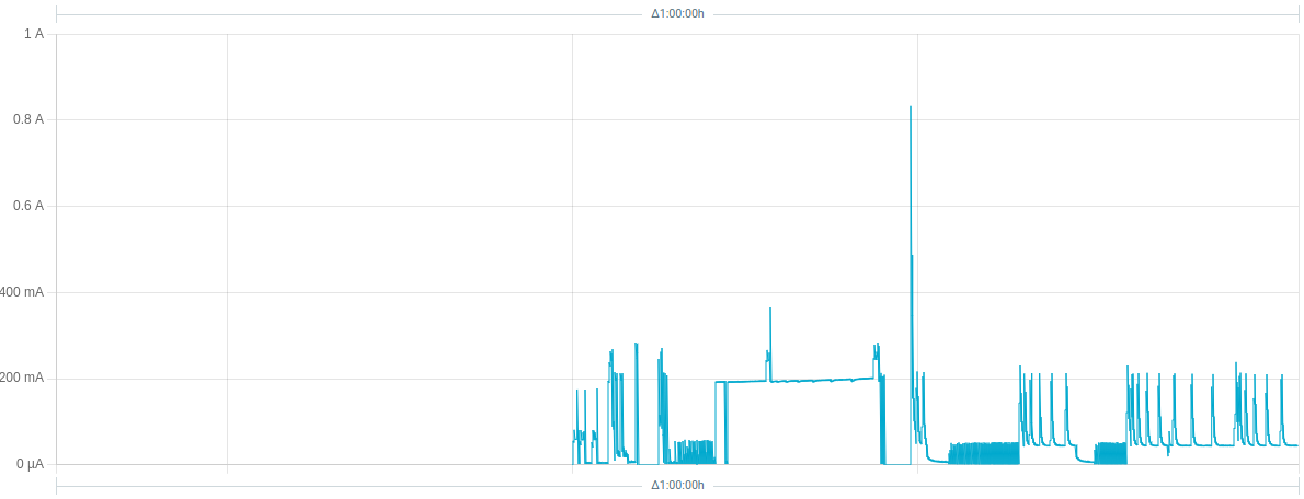
Extended test -- note, test begins with largest spike:
External power or Eable
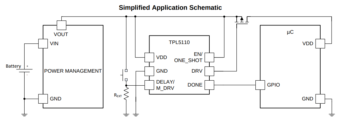
We also have a TPL5110 breakout, which rather than setting an enable pin high/low, connects and disconnects power. The TPL5111 breakout is best when you have an enable pin you can control, the TPL5110 is best when you are able to 'break' the power input line to place the TPL5110 between the power supply and Vin.
TPL5110
TPL5110 connects and disconnects power -- best for when you can cut the power supply
Note: Sparkfun makes a nice breakout board for the TPL5110 that includes switches for the resistance value! On digikey here
and on Sparkfun here
TPL5111
TPL5111 ideally sets an enable pin high/low -- best for when there's an enable pin on an LDO
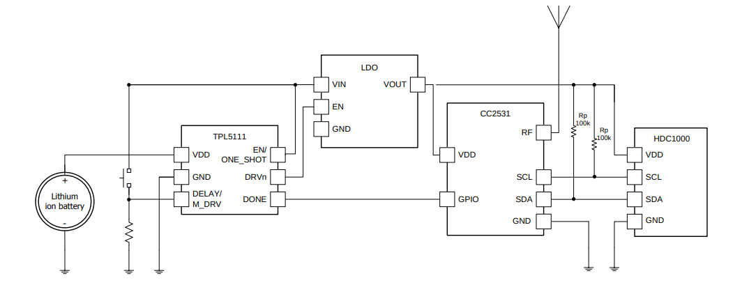
Actually, seems as though we might want TPL5111 -- controlling an enable (or reset) pin -- since we need to keep the satellite modem powered. And in general we can expect that an enable / reset approach is quite flexible -- we can design our own LDO / mosfet setups in general.
So, how would an a TPL5111 setup work?
Reading the Adafruit guide to the TPL5111, here ...
Note that the TPL5111 pulls an enable pin high -- if we wanted to invert the signal, we could use a single chip for that, or resistors and a transistor, as per https://electronics.stackexchange.com/questions/30238/how-to-invert-a-digital-signal
Usage is easy. First, set your desired delay but adjusting the on-board trim pot: all the way to the left is once-per-100ms an all the way to the right is once-every-2-hours. Then, connect VDD up to your 3-5V project power supply, and then your project's enable pin to the Enable pin. Finally, select a signal pin from your project to the Done pin. In your project's code or design, just make sure that it sets the Done pin high once it is completed with it's task. That's it!
Now that I'm looking at it -- these chips are intended to create a low-power state. For a simple remote sensor application, this might be ideal. For the satellite modem use-case, it's unclear. Perhaps I could use the pin state to pull EN low on the micro and the satellite modem?
External watchdog timer
Digikey very good guide to watchdog timers
Note in that writeup that the ADM6316 seems suited to 'pushing a reset button' -- has a "push-pull" driver -- digikey listing here and datasheet here
Sat modem behavior
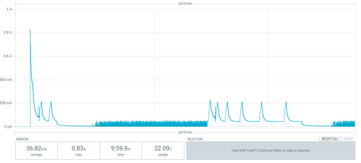
Looks like 100K is too 'weak' a pulldown to force the sat modem pin down. 10K seems to work.
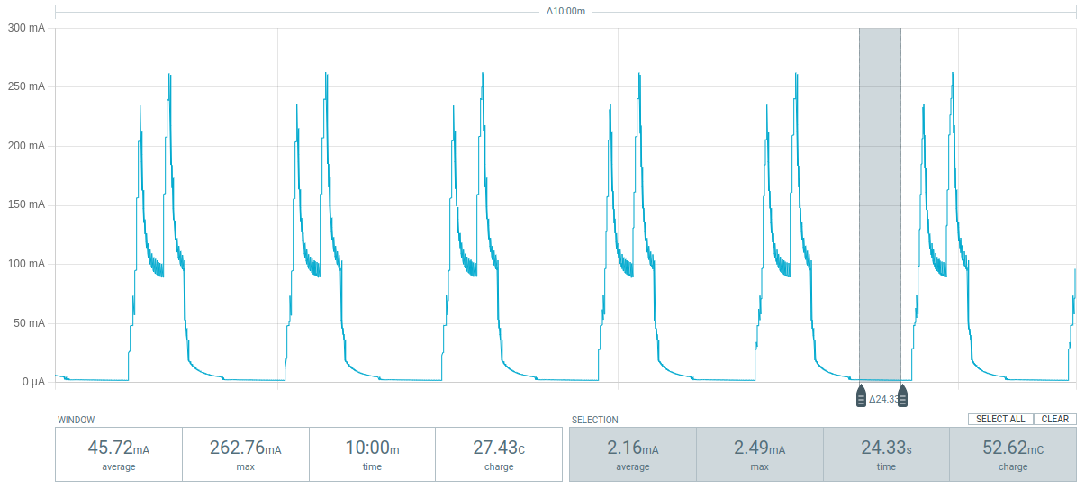 |
|---|
| Fig 1. Using a 10K pull-down on the satellite "enable" pin. Large double-pulse in current is due to satellite modem turning on when microcontroller pulls enable pin high. When micro deep sleeps, it seems to 'let go' of the control pin; but 10K pull-down forces it to ground. Resultant sleep current with micro + sleeping sat modem seems to be around 2 mA. Note that sleep current of sat modem without micro seemed to reach at least as low as 200 uA (perhaps would trend lower given more time). |
Also: it seems as though there is an initial 'charge up' period before the satellite modem will turn on at all; so pulling up the EN pin on it appears to have no effect initially.
At 3.3V, a 10K resistor yields a 'leakage' current of .3 mA ... which is significant, but our current sleep current for the micro seems to be approx 4 mA anyway ...
Can find a more sophisticated way to pull up / down with additional circuitry.
Quick thoughts on setup
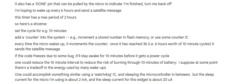
Using a TL5110 would allow the system to sleep at very low current. It could power the micro; the satellite modem would be powered independently; the EN pin on the sat modem would be pulled own by default. The micro could wake every X minutes.
However, the micro retains no memory when it's asleep (powered off, or deep sleep). So it could only ever wake up and try to send a satellite message.
It would need some way of storing some counter to see whether it should send a message or not when it wakes up.
Unless 2 hours is okay as a start.
Checking the time via GPS doesn't work -- wouldn't know how much time had elapsed without some storage mechanism.
Does DS3231 have some general memory we could use?
Trouble: if something goes wrong in the 'counting' code, or the storage mechanism, then we might never conclude that we ought to send a message.
Best is if the system can be turned on every X hours, do its thing, then turned off.
Maybe there's some hardware counter than can help.
Turn on every 2 hours. Every time it turns on, it makes the counter progress. Read the counter on wakeup; if the counter has reached Y counts, then try satellite.
Waking up an arduino with the DS3231: https://www.youtube.com/watch?v=-dW4XsBo3Mk
Failsafe design for space: https://www.mouser.com/applications/electronic-systems-space-require-fail-safe/
pros / cons of various memory approaches: https://www.digikey.com/en/articles/the-fundamentals-of-embedded-memory
Proposal A
Interfacing with the microSD card
Adafruit guide to microSD and Circuitpython
Issues with the TPL5110
https://electronics.stackexchange.com/questions/390139/tpl5110-doesnt-work-with-nodemcu
Interesting ... adding caps on VDD / GND didn't do it for me, using the Feather ESP32-S2 + TFT
What seems to work is to add a stronger pull-down resistor on the "DONE" pin.
When I added 45K, the micro didn't wake up fully.
When I changed it to 4.5K, the micro woke up.
The default resistor on the TPL5110 board from adafruit is 1M to ground -- seemingly far too weak for our purposes here.
Hmm -- oddly, seems as though the 'shutoff' works when DONE is connected to A1, even though the firmware points at D5. If I connect to D5, it shuts off too soon.
Going to experiment with other pins ...
Perhaps there is something strange about e.g. D5 ...
Oh wait -- the code was actually changing A1 still ...
Okay, changing code to A1 ...
A1 works.
Trying D5 ...
Interesting! D5 doesn't work, but A1 does ...
Note that A1 is pulled to ground with a bodged resistor, too ...
value: also 4.4K!
i.e. we have two 4.4K resistors in parallel ... equalling 2.2K
What if we tried D5 with the same setup -- parallel 4.4K resistors as a pulldown?
Cool, works!
Now try with the power recording tool ...
... doesn't work for some reason.
System works using an ItsyBitsy BLE, running of 5V to VDD into the TPL5110 board. Also works off 3V pin on IB.
Something wrong with the power measurement device?
Ah, mystery continues ...
The power profiler works when the itsy bitsy is in the loop -- i.e. when the input power is connected to '3V' on the IB board.
Let me also test with 'USB' pin ...
Yes, seems to work.
Perhaps this is b/c of the capacitors on the IB board ... I can look them up quickly ...
Schematic is here: https://cdn-learn.adafruit.com/assets/assets/000/087/158/original/adafruit_products_schem.png?1579387035
Looks like the max we have is a 10uF cap ...
.. so let's try a 10uF cap between VDD and GND (which, TBH, may be what we removed from the TPL5110 board in the first place ...)
YES, 10 uF cap works!
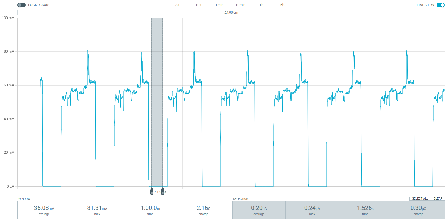
Result: .2 uA sleep current ... pretty great!
Summary:
- used sweet-p/firmware/board_ver_0.2/v6.0/test_tpl_code.py
- used pin D5
- two parallel 4.4K resistors pull-down to ground
- 10uF cap on VDD + GND on the TPL
Note: the TPL5110 board had a 1uF cap -- let me quickly test with that ...
Didn't seem to work! So, 10uF is a useful addition ... if we're using the TPL5110 breakout, we should add it in parallel on VDD and GND ...
Update: tested the 'original' code -- with microSD and LoRa broadcast -- with a resistance that results in a longer period -- approx 20 secs -- and it all seems to work!
Note -- looks as though various of the ESP8266 pins fluctuate on boot -- which may have been another issue affecting satellite pull-down, and now the TPL5110 pull- down.
See "All ESP8266 pins oscillate at boot, except GPIO4 and GPIO5." & etc post, here (same link as above)