Edge Collective
Upgrades after lightning strike
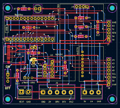
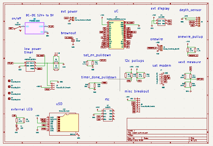
Taking the opportunity to simplify the overall circuit.Circuitpython code for identifying possible uart pin pair combinations: https://learn.adafruit.com/adafruit-itsybitsy-nrf52840-express/circuitpython-uart-serial
IB NRF
Looks like any pin combinations work
IB M4
RX pin: board.A3         TX pin: board.A2
RX pin: board.D4         TX pin: board.A2
RX pin: board.D5         TX pin: board.A2
RX pin: board.SDA        TX pin: board.A2
RX pin: board.A1         TX pin: board.A4
RX pin: board.A5         TX pin: board.A4
RX pin: board.D2         TX pin: board.A4
RX pin: board.D0         TX pin: board.D1
RX pin: board.D10        TX pin: board.D1
RX pin: board.D11        TX pin: board.D1
RX pin: board.D12        TX pin: board.D1
RX pin: board.D9         TX pin: board.D1
RX pin: board.D10        TX pin: board.D12
RX pin: board.D11        TX pin: board.D12
RX pin: board.LED        TX pin: board.D12
RX pin: board.D3         TX pin: board.D12
RX pin: board.APA102_MOSI        TX pin: board.D12
RX pin: board.D0         TX pin: board.LED
RX pin: board.D10        TX pin: board.LED
RX pin: board.D11        TX pin: board.LED
RX pin: board.D12        TX pin: board.LED
RX pin: board.D9         TX pin: board.LED
RX pin: board.D10        TX pin: board.APA102_SCK
RX pin: board.D11        TX pin: board.APA102_SCK
RX pin: board.LED        TX pin: board.APA102_SCK
RX pin: board.D3         TX pin: board.APA102_SCK
RX pin: board.APA102_MOSI        TX pin: board.APA102_SCK
RX pin: board.A3         TX pin: board.SCL
RX pin: board.D4         TX pin: board.SCL
RX pin: board.D5         TX pin: board.SCL
RX pin: board.SDA        TX pin: board.SCL
RX pin: board.D4         TX pin: board.SDA
RX pin: board.D5         TX pin: board.SDA
RX pin: board.SCL        TX pin: board.SDA
IB KB RP2040
RX pin: board.A3         TX pin: board.A2
RX pin: board.RX         TX pin: board.A2
RX pin: board.SCL        TX pin: board.A2
RX pin: board.A3         TX pin: board.TX
RX pin: board.RX         TX pin: board.TX
RX pin: board.SCL        TX pin: board.TX
RX pin: board.A3         TX pin: board.SDA
RX pin: board.RX         TX pin: board.SDA
RX pin: board.SCL        TX pin: board.SDA
RX pin: board.D5         TX pin: board.D4
RX pin: board.D9         TX pin: board.D4
RX pin: board.D5         TX pin: board.D8
RX pin: board.D9         TX pin: board.D8
RX pin: board.D5         TX pin: board.MISO
RX pin: board.D9         TX pin: board.MISO
Fri Nov 1 07:53:17 PM EDT 2024
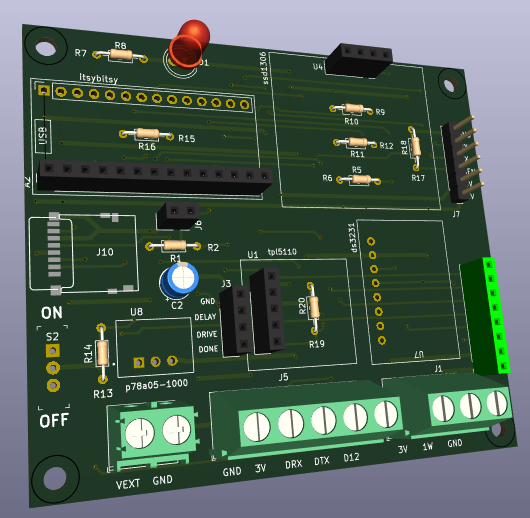
Figuring out where to place the capacitor on the new board, based on where it was last time
330 uF cap was placed between DRIVE and GND
NOTE: the depth sensor should receive on the 'created' UART -- only need to coordinate the RX pin -- while the satellite modem should have the 'true' board UART as defined.
Sat Nov 2 10:19:42 AM EDT 2024
Using SPI bus on battery with NRF -- https://learn.adafruit.com/adafruit-itsybitsy-nrf52840-express/caution-using-spi-on-battery-power -- need the special code on this page.
import busio, board
# Allocate and then don't use the first SPI object.
# Choose pins you are not otherwise using. The pins below are just examples.
# You only need to specify a clock and a MOSI pin.

# Will allocate but not use SPIM3. SPIM3 doesn't work when not powered by USB.
do_not_use_this_spi = busio.SPI(clock=board.A0, MOSI=board.A1)

# Will allocate one of the working SPIM peripherals.
spi = board.SPI()

# ..
Update: going to choose D2 as RX for depth sensor, and A4 as TX (likely not needed); this works for M4 and NRF; other micros can use analog input if necessary. board.RX and board.TX get connected to sat modem.