Edge Collective
UV Spectrophotometry
Designing a DIY UV SpectrophotometerQuick links
Background
Kearns et al have been working to develop lower-cost methods of testing that leverage a particular feature of biochar (and similar filters): some contaminants adbsorb much more easily than others. It turns out that the presence of one class of more weakly-adsorbed contaminants -- dissolved organic matter -- is relatively easy to assess with a lower-cost laboratory method: UV spectrophotometry.
The details of this approach are laid out in a 2020 article by Kearns et al:
- "Biochar Water Treatment for Control of Organic Micropollutants with UVA Surrogate Monitoring" -- https://www.liebertpub.com/doi/full/10.1089/ees.2020.0173 | PDF | local PDF
And specific instructions for performing the UV absorbance test are laid out in the supplementary section, here:
Further: while commercial UV spectrophotometers used in such tests are usually over $2000, there are several designs available for DIY forms of the instrument, costing under $100 in parts. We found one design to be particularly simple and well-characterized:
- "An accurate, precise, and affordable light emitting diode spectrophotometer for drinking water and other testing with limited resources" -- https://www.ncbi.nlm.nih.gov/pmc/articles/PMC6988917/
Our aim is to build a working prototype of this UV spectrophotometer, compare its performance to similar commercial instruments used in a laboratory, and then see if such an instrument might be easy to build and use in a community workshop setting.
Misc notes
-
Josh Kearns substack piece on Kearns et. al, "Leveraging DOM UV absorbance and fluorescence to accurately predict and monitor short-chain PFAS removal by fixed-bed carbon adsorbers"
-
Analog Devices article by L. Orozco, "Synchronous Detectors Facilitate Precision Low-Level Measurements"
Sun Mar 3 08:35:31 PM EST 2024
Building the circuit
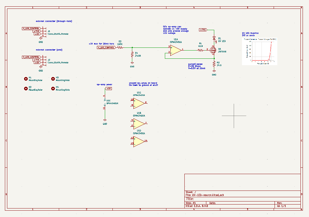
Precision voltage to current converter
Adafruit 4-pin jumper cable here
Adafruit 4-pin jst ph stemma here
Adafruit JST 4-pin jst ph stemma SMD here
- diagram here
Mon Mar 11 05:20:16 PM EDT 2024
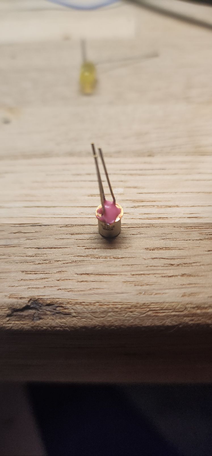
LED polarity 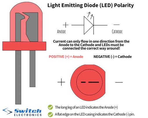
uv detector IN-C35PPCTGU0
datasheet here
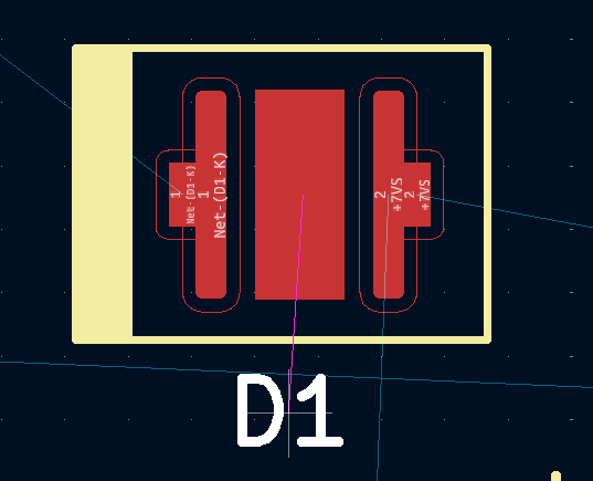
custom footprint:
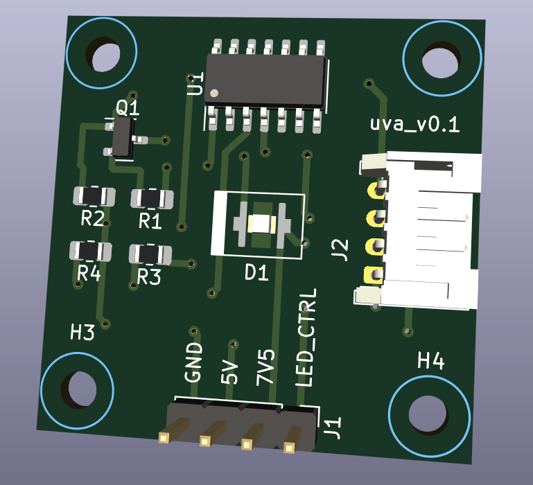
emitter v_0.1 ordered 3/11/24
detector v_0.1 ordered 3/12/24
Fri Mar 15 11:00:43 AM EDT 2024
instructrable on 555 as switch mode supply
Sat Mar 23 03:52:20 PM EDT 2024
Solder mask goof-up on UV emitter part!
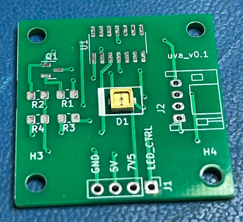
Reference for UV emitter IN-C35PPCTGU0
Also: two pins on Q1 on emitter are 'flipped' -- need to fix pins -- was able to solder 'upside-down' anyway to fix
Mon Mar 25 08:17:39 PM EDT 2024
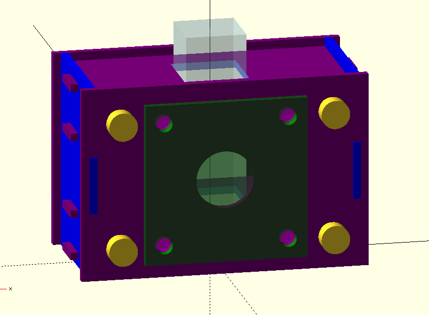
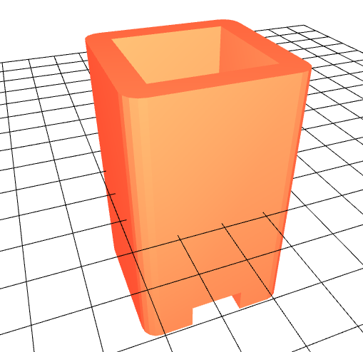
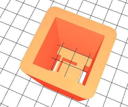
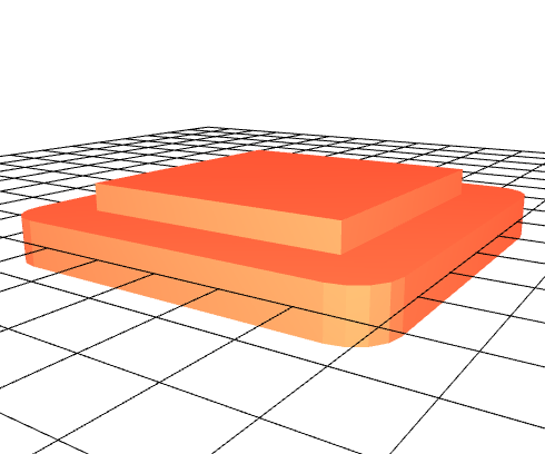
Made a quick 3d enclosure using openscad:
openscad and stl files are here
Fri Mar 29 08:57:08 PM EDT 2024
Water filtering, 1 micron
Selection at McMaster here
Nice pairing on Amazon:
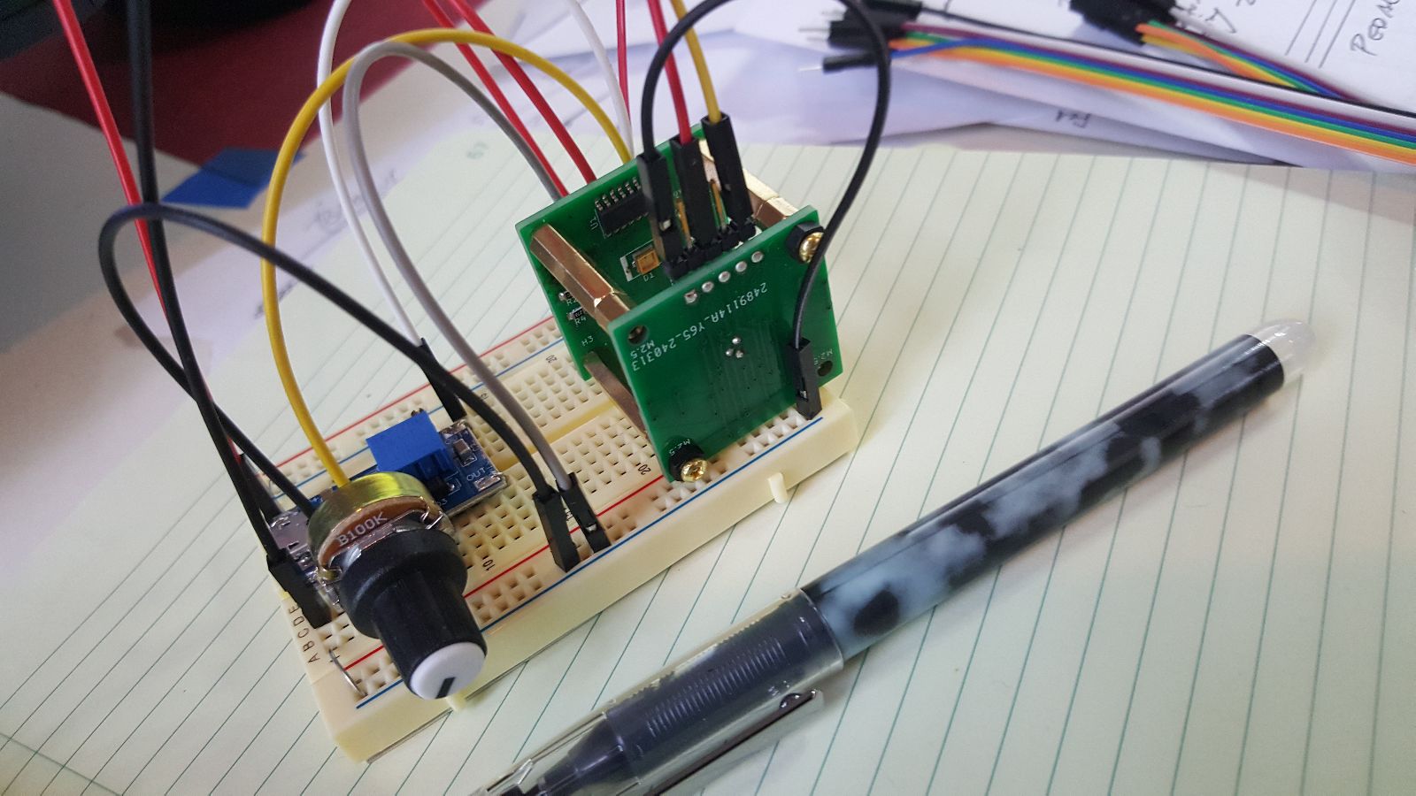
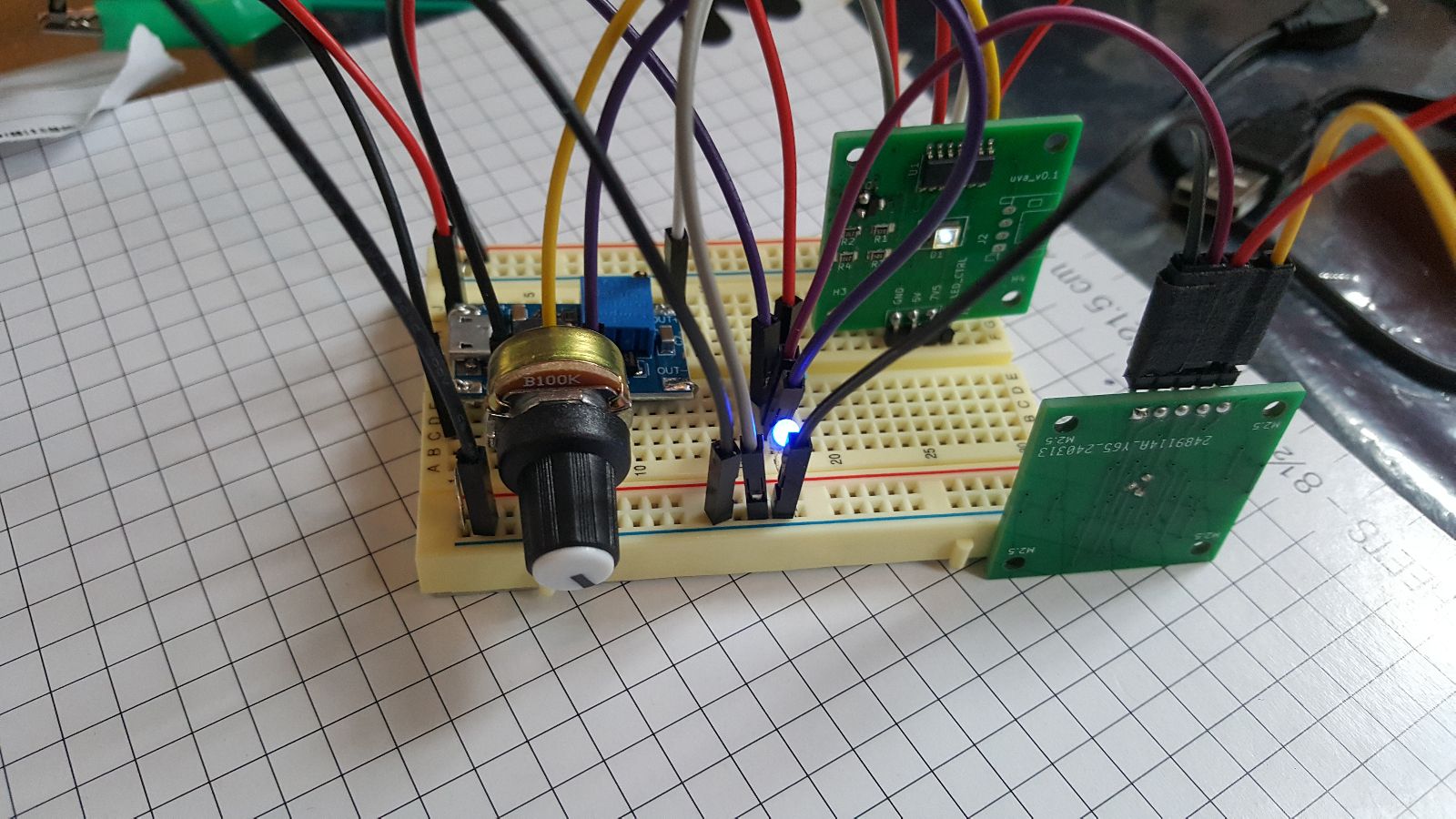
Most recent prototype
Fri Apr 5 08:31:52 PM EDT 2024
Working on detector v_0.2 ...
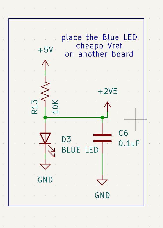
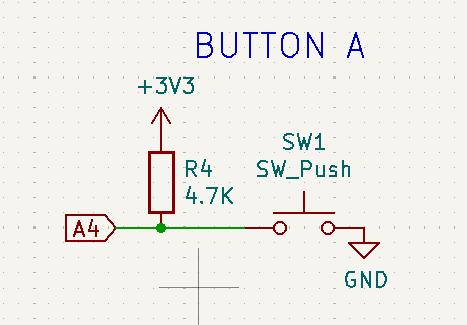
Sub-schematic that will be moved to a 'control board':
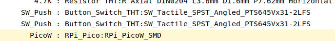
Version 0.1 footprint assignments:
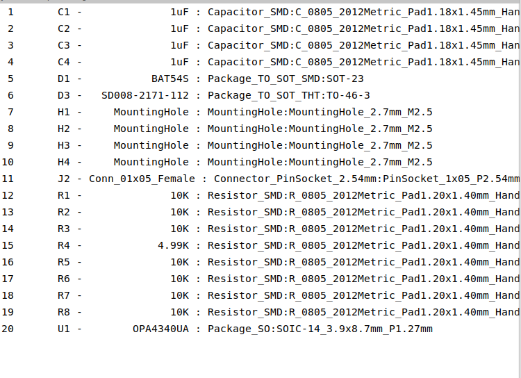
Version 0.1 pinout:
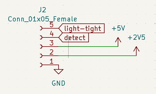
(need to add 2.5V ref)
Fri Apr 5 11:01:04 PM EDT 2024
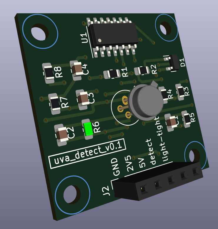
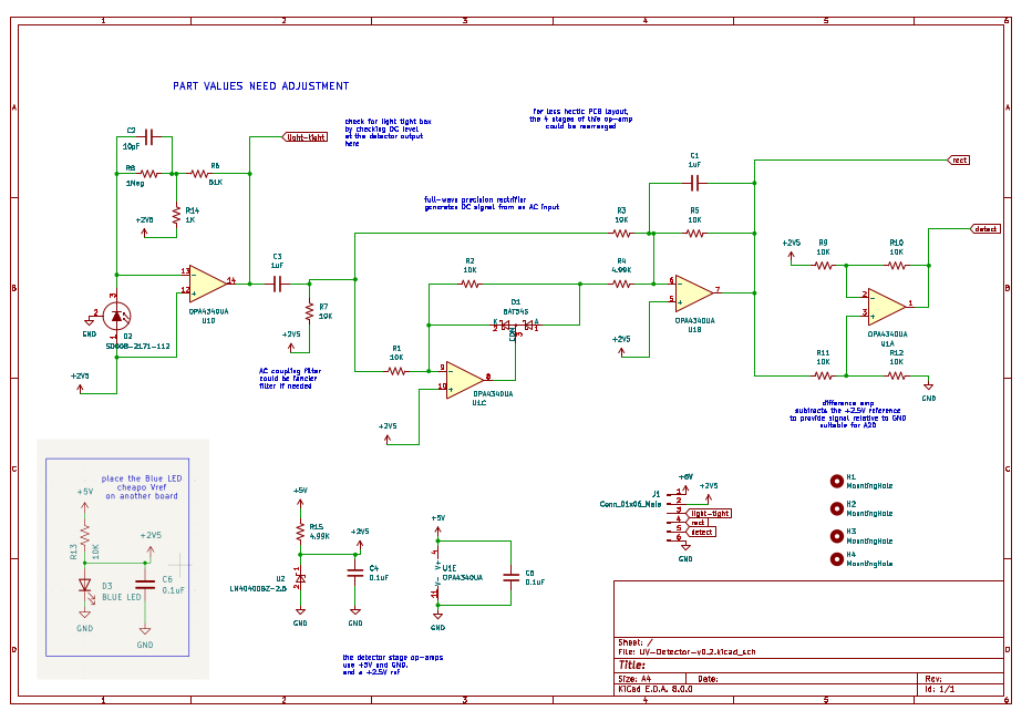
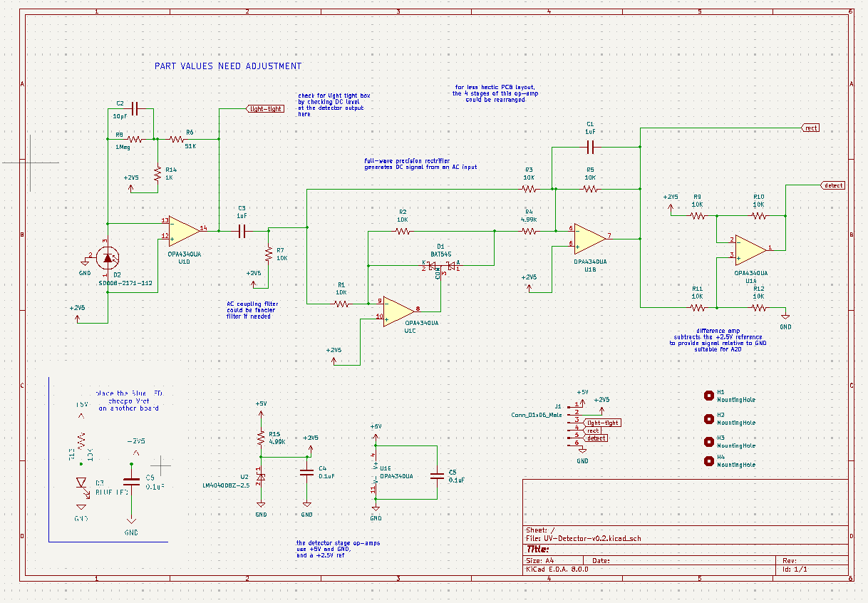
Detector schematic:
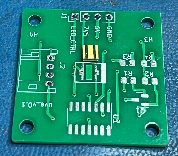
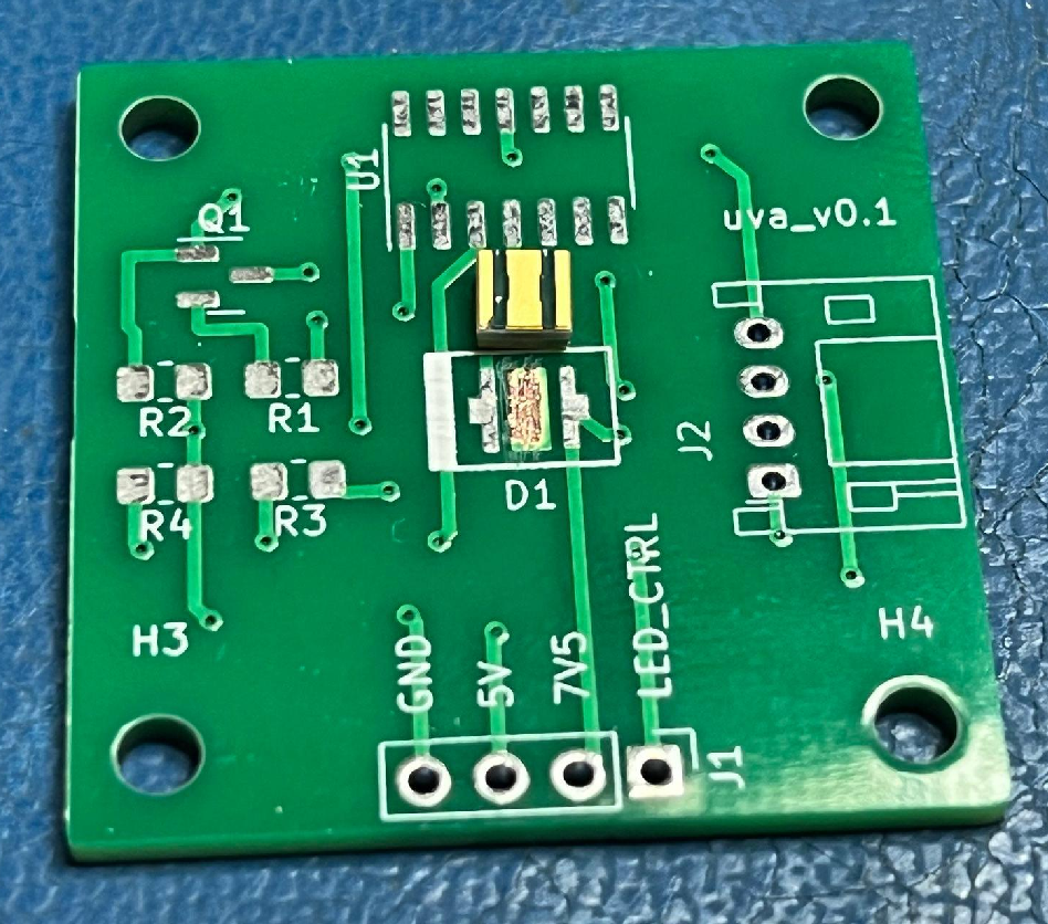
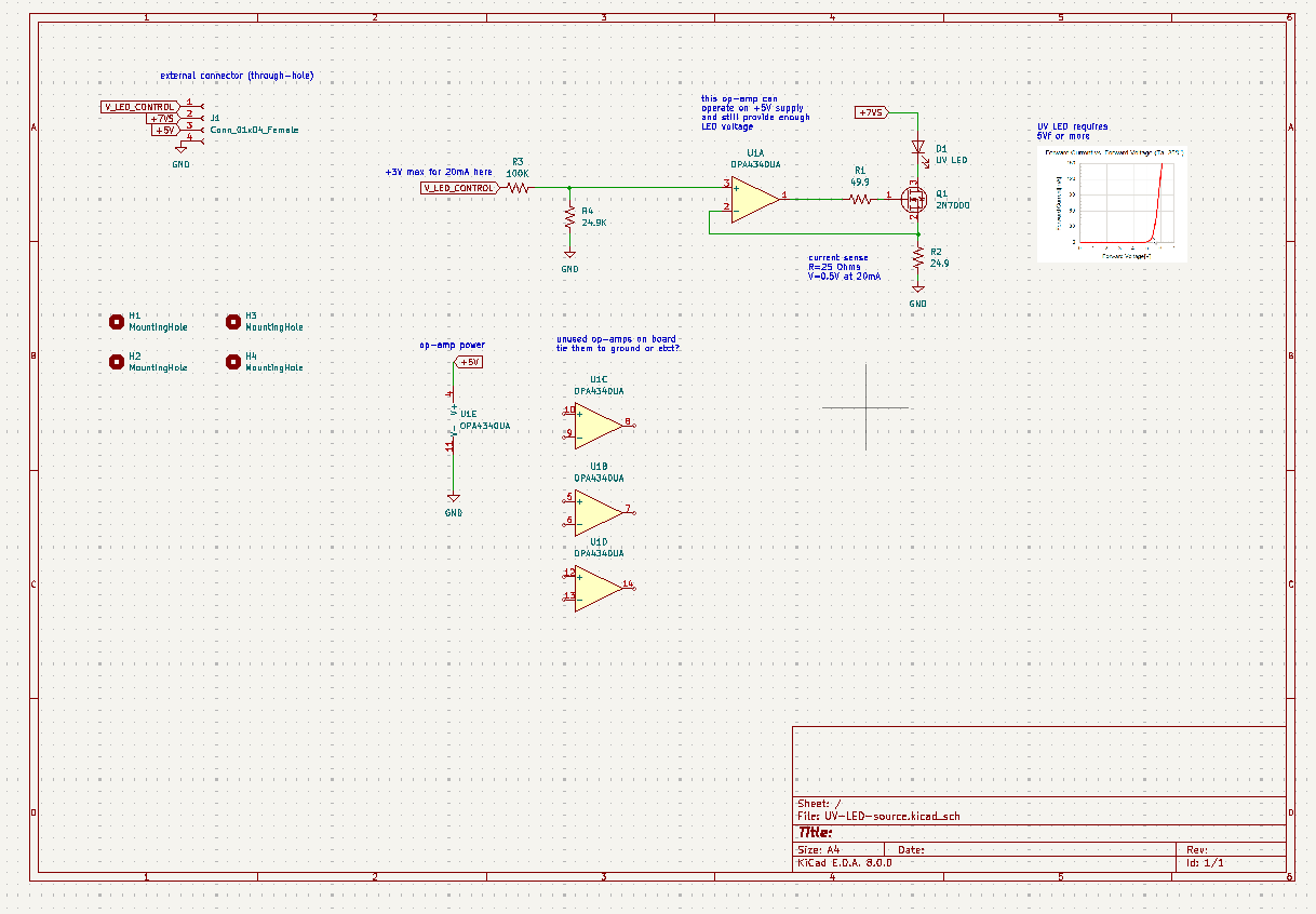
Emitter schematic:
Revision 0.2 of emitter and detector
Sat Apr 6 10:25:06 PM EDT 2024
Edited footprint for LED (remove solder mask from center pad)
Revising mosfet pin assignment on emitter ...
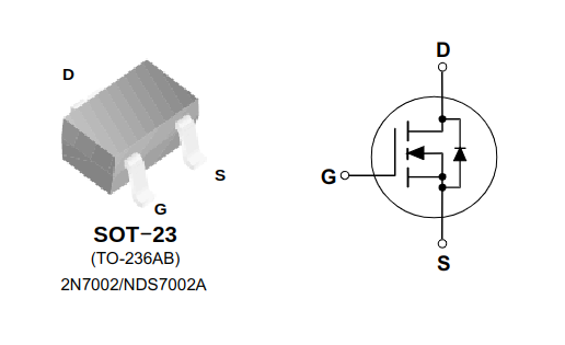
2N7000 pinout:
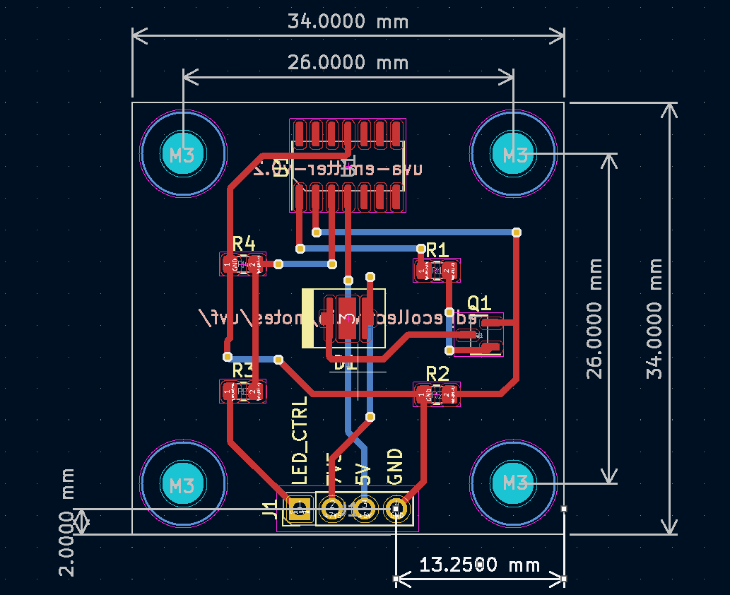
emitter ver 0.2
Sat Apr 6 10:22:42 PM EDT 2024
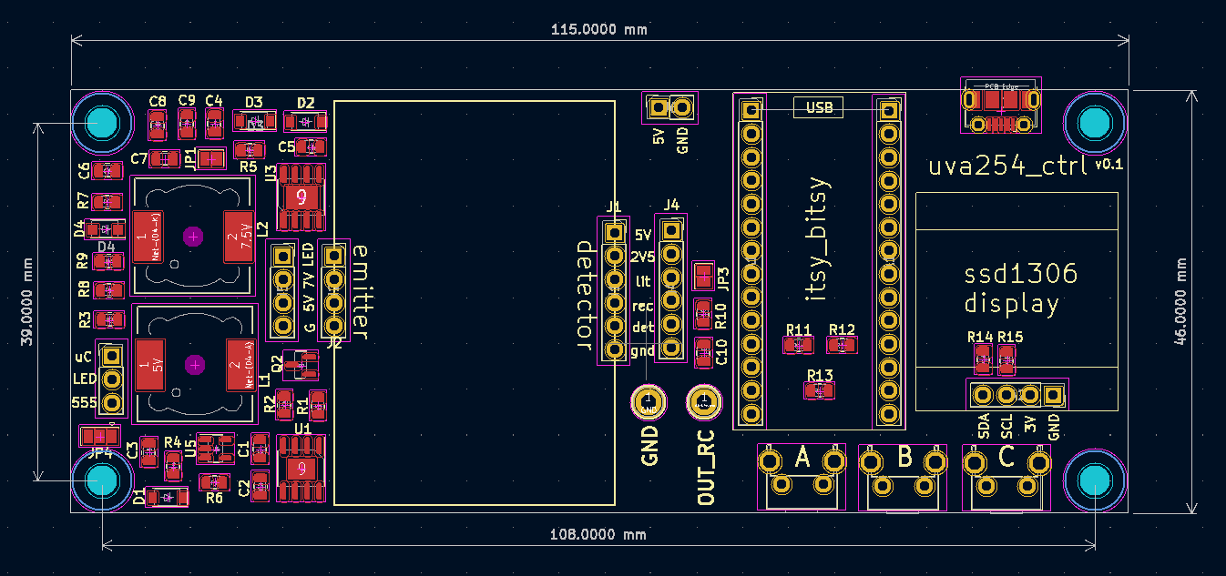
board layout:
schematic:
 )
)
board files:
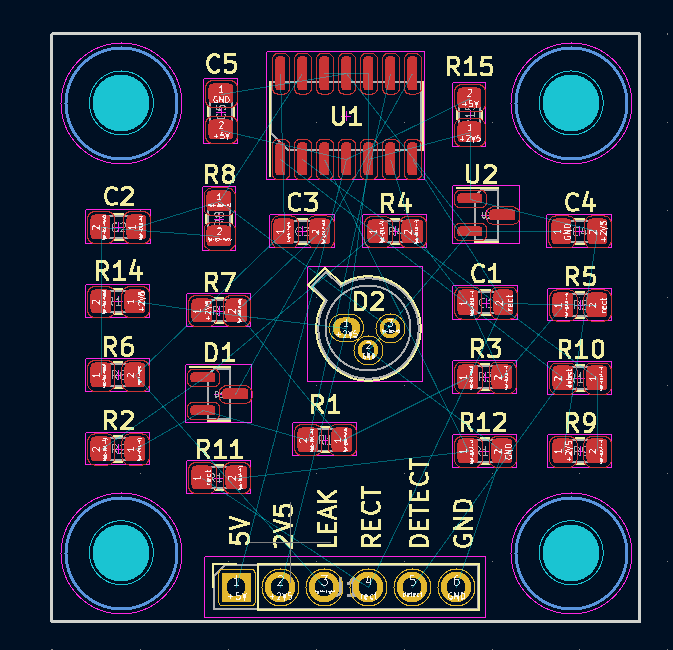
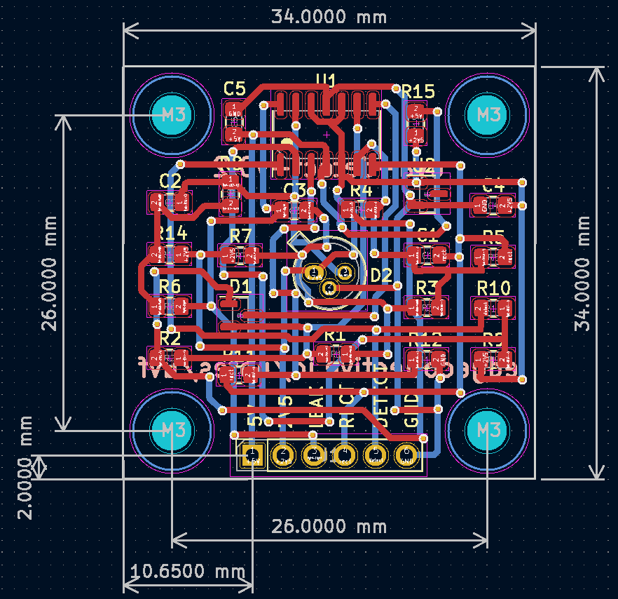
detector ver 0.2
Sat Apr 6 10:22:55 PM EDT 2024
board layout:
schematic:
 )
)
board files:
Mon Apr 15 08:18:11 PM EDT 2024
Collecting water samples and filtering through 1 um filter ...
3/4" NPT male + 3/4" barb fitting on Amazon
electric water transfer pump on Amazon
calibration of total organic carbon / uv254, EPA document pdf
'request a quote' for uva254 go here
might want to search for 'total organic carbon' (TOC)
An easy spectrophotometric acid-base titration protocol for dissolved organic matter
correlating uv254 to TOC, BOD, and COD video
Great paper on UV254 methods and applications. Note: correlations between uv254 and disinfection byproducts! references here
Mon Apr 29 09:29:59 PM EDT 2024
UV-Vis spec of Organic Compounds
UV-Vis spec, student resources
Nice general reference on uv-vis spec
Some UV-Vis chemistry examples
Sun May 5 02:54:23 PM EDT 2024
Notes on testing v0.2
idea: place all non-emitter/detector components on 'bottom' of board to allow easy access during testing
use voltage doubler on emitter board, as per this part here
replace the 5K R15 on detector board with R15 = 619 ohms
add current sense breakout above R2 on emitter board
add 555 boost and 555 emitter input on external feather board
add usb socket to motherboard for power
I was getting a measly 1.0V at the "2V5" reference pin - some buffoon (that is, me) seems to have chosen poorly the value of R15. I have replaced the 5K with a 619 Ohm resistor - and much better! I get 2.5Vreference.
And the signal at "leak" seems to act as I expected, in room light anyway. I still have to set up the LED and test a blank and wet cuvette ...
so, that T-network has a nice high gain!
And the input signal is 2.491 to 2.517 at 1kHz
Implies the equivalent feedback R is about 53.8Meg
There about 26nApp into the the stage with this test
So , 26mVpp into 1Meg for test current, and about 1.4Vpp output
Now to find what I did wrong at the LED stage ...
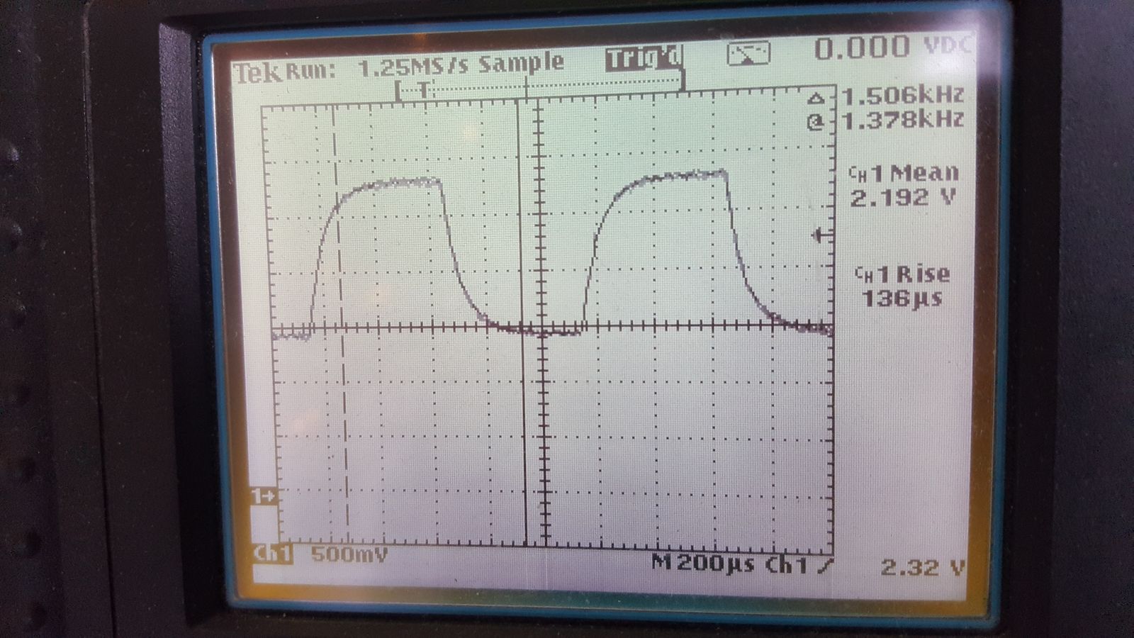
With 130us rise time that's about 2.7kHz tia bandwidth
Don't run the LED at 10kHz ..
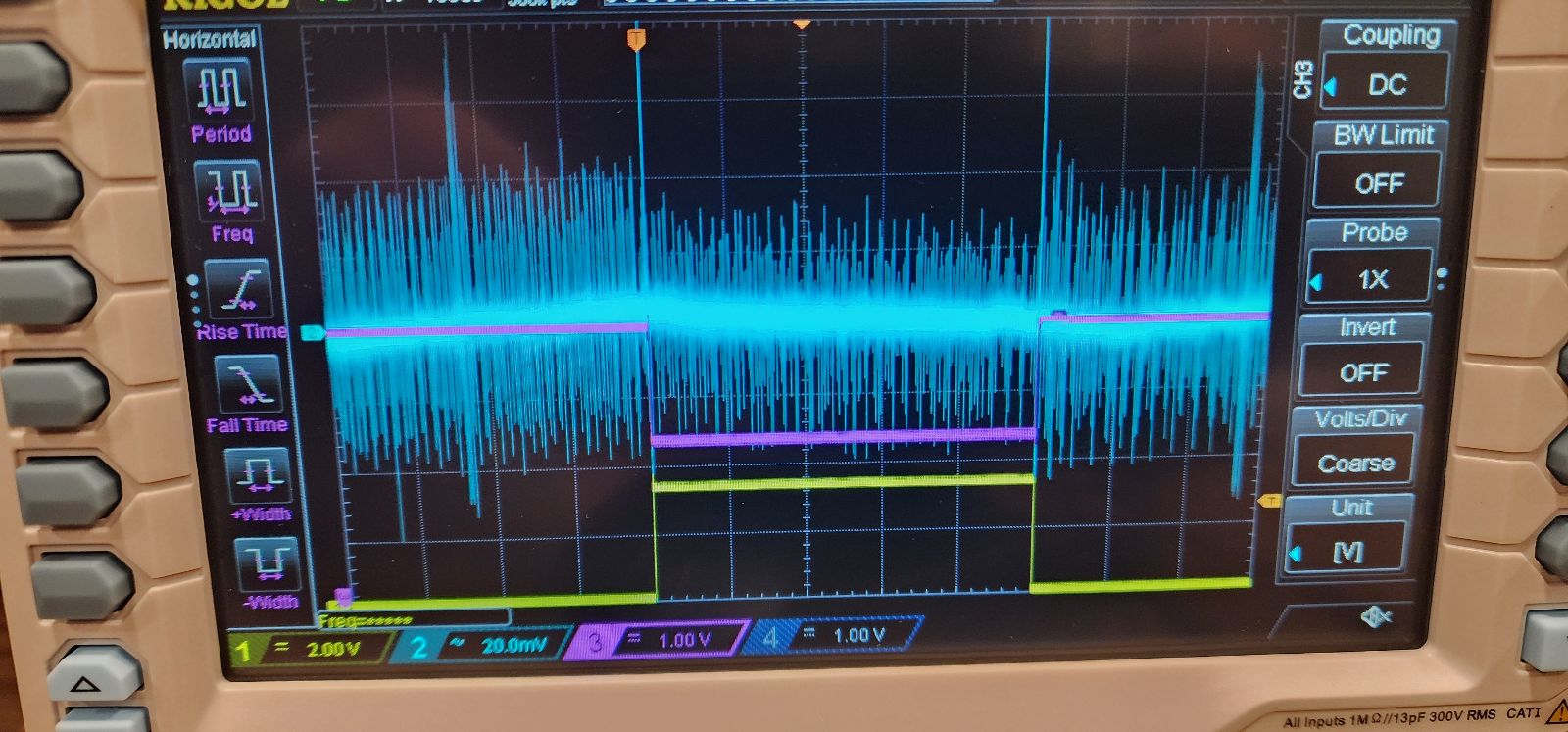
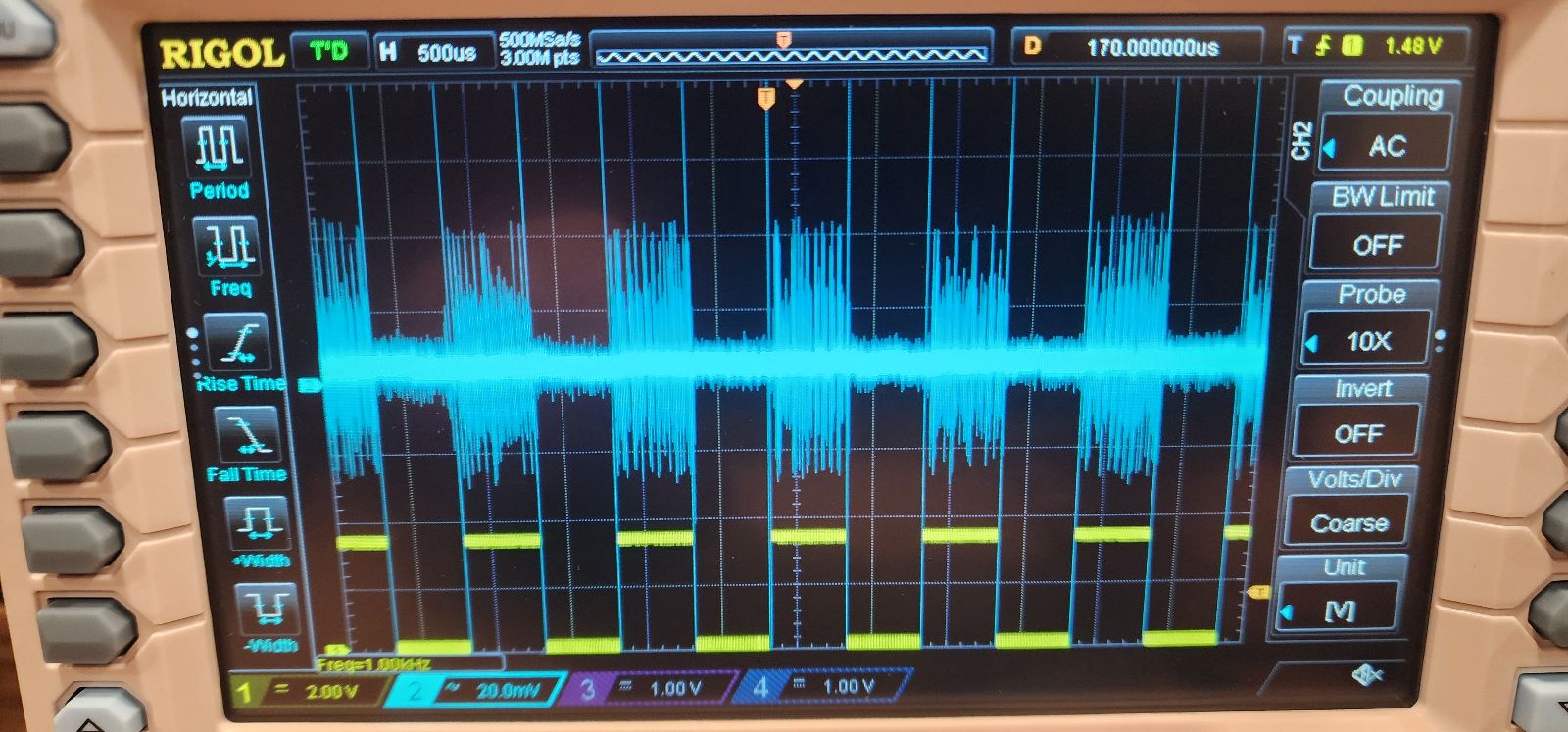
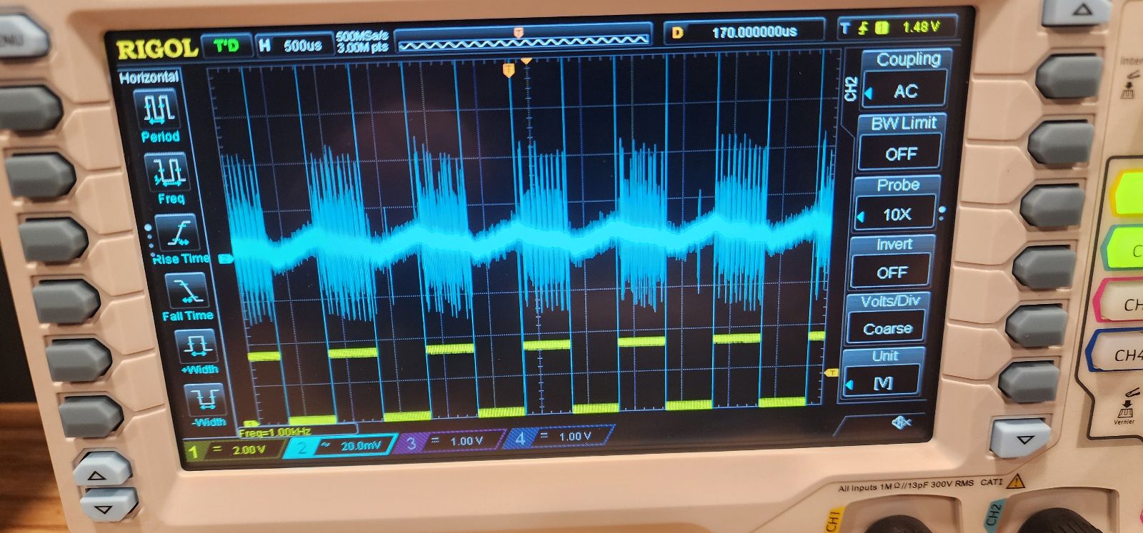
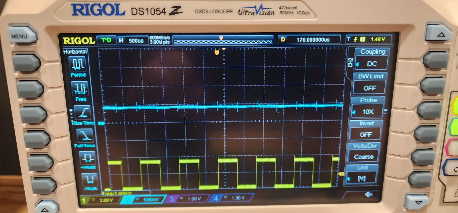
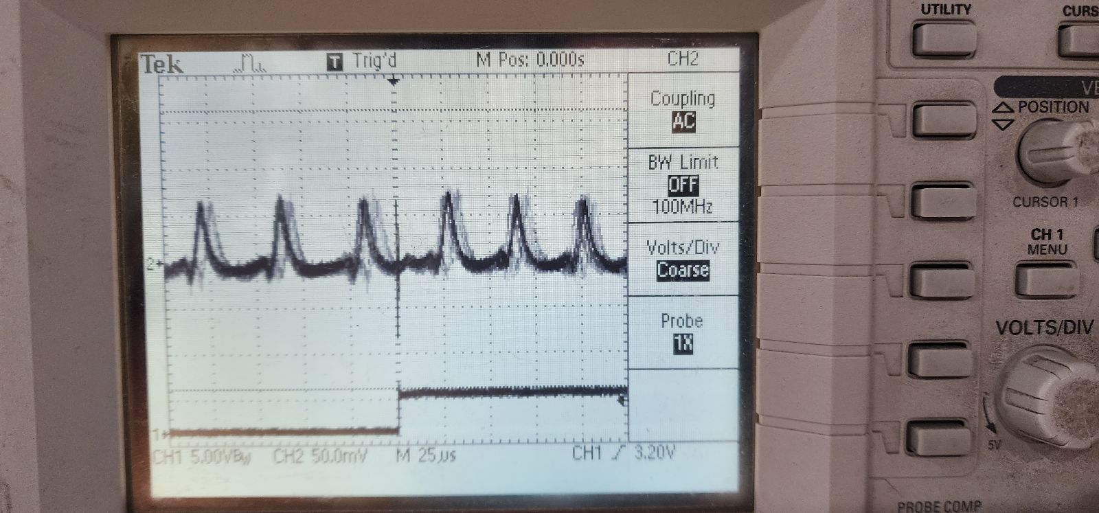
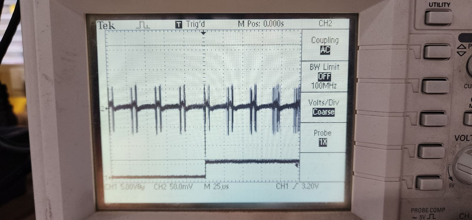
OK I have a solid 0.5Vpp signal at "leak" node when I ping the LED board with 0V to 3V square wave at 500 Hz. On that emitter pcb I had to swap out R1 (was 49.9K) to 49.9 Ohms, and R2 (was 24.9K) to 24.9 Ohms. So, no cuvette, in the opto-mechanical system Craig designed, I see 0.5Vpp signal. Not bad.
less nice, I see some noise - I think that high gain TIA is also picking up 60Hz, and some other crap. more scope-ing to figure this out .... maybe we want a metal box ?
Fri May 10 03:39:30 PM EDT 2024

Fri May 17 08:25:56 PM EDT 2024
Version 0.2 of hardware does indeed work!
Input: 1 kHz square wave, 50% duty cycle, 3.3V pp
 |
|---|
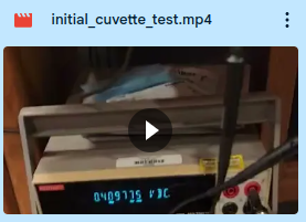
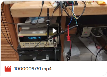
| Video of initial test with cuvette filled with distilled water. Interesting: voltage at DETECT slightly higher with liquid-filled cuvette than without any cuvette ... lens effect? |
 |
|---|
| Raw battery sag is about 0.2V |
 |
|---|
| Test setup |
 |
|---|
| LEAK blocked |
 |
|---|
| LEAK unblocked |
 |
|---|
| RECT blocked |
 |
|---|
| RECT unblocked |
 |
|---|
| DETECT blocked |
 |
|---|
| DETECT unblocked |
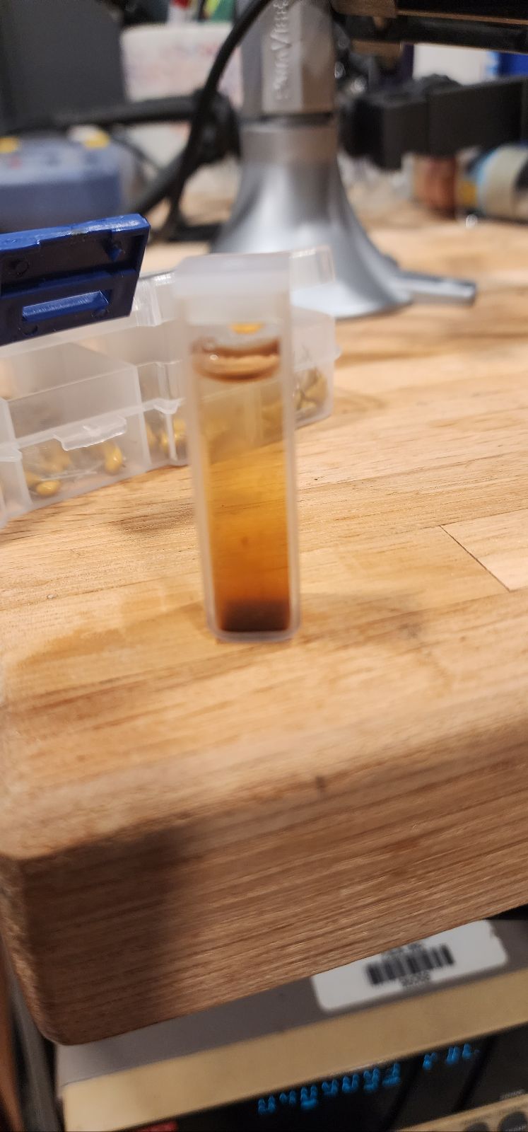
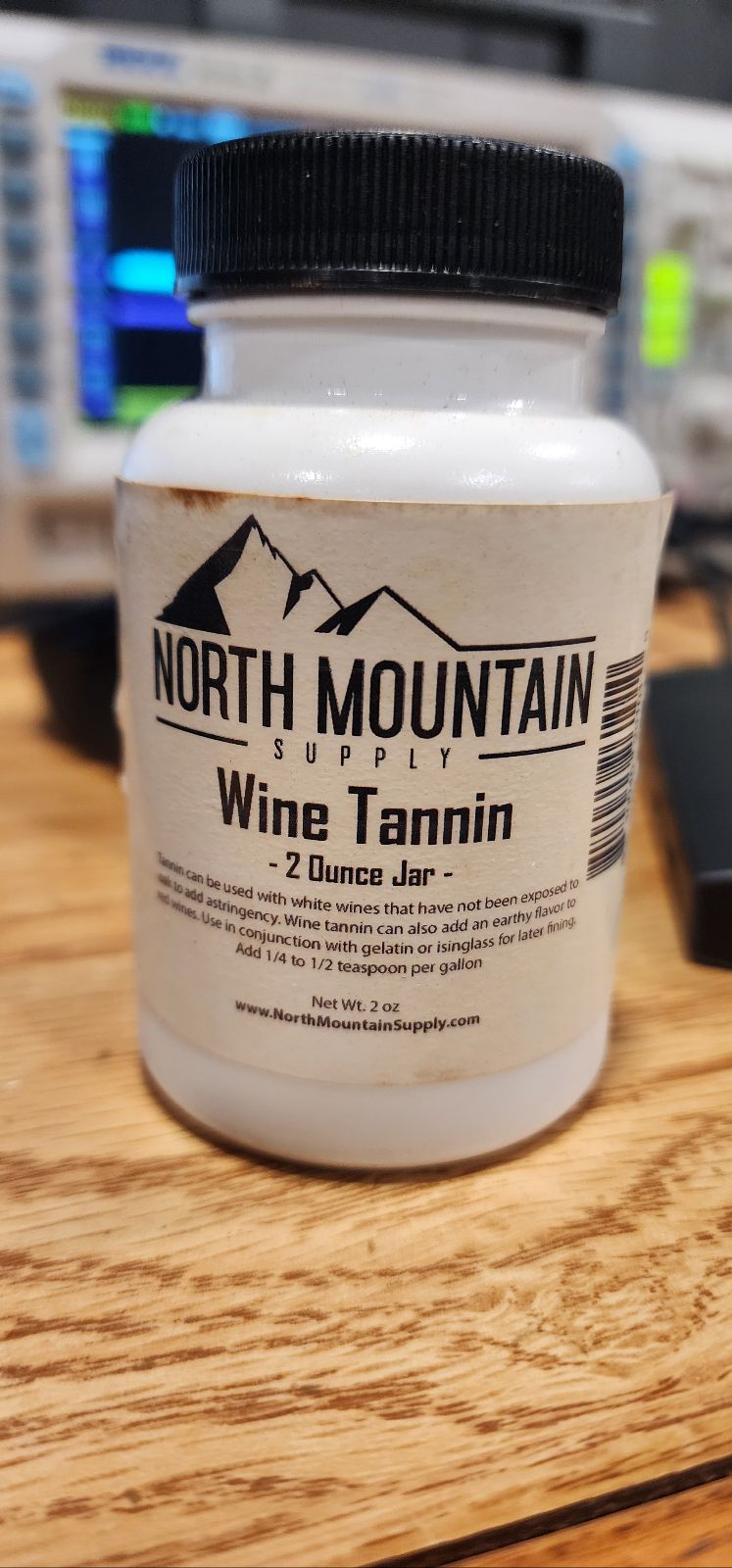
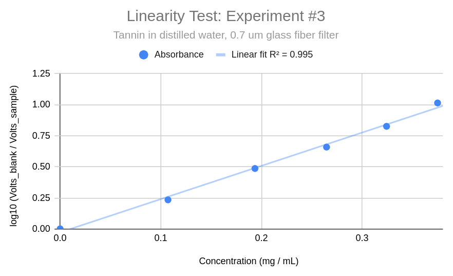
Initial 'linearity test' attempt using tannin powder
 |
|---|
| Video of initial tannin test. Initial solution: 25 mg tannin powder in 5 mL of distilled water (this dropped DETECT signal to 'zero'); then diluted 5 mL of that solution into 25 mL of distilled water. |
Next steps:
- DC-DC boost noise reduction via 555-based circuit
- test of linearity of circuit
- 555-based 1 kHz input
- respin case to enhance internal light collimation
- ground plane on board and 60 Hz shielding
Sun May 19 06:02:51 PM EDT 2024
Similar platform: https://iorodeo.com/products/uv-open-colorimeter
- colorimeter product guide: https://blog.iorodeo.com/open-colorimeter-product-guide/
- uv sensor board in particular https://iorodeo.com/products/as7331-uv-sensor-board?pr_prod_strat=e5_desc&pr_rec_id=037acace2&pr_rec_pid=7328730316915&pr_ref_pid=7363616571507&pr_seq=uniform
- current-controlled LED board https://github.com/iorodeo/i_control_led
What would be required to make their system work for UV254?
Sun May 26 01:51:00 PM EDT 2024
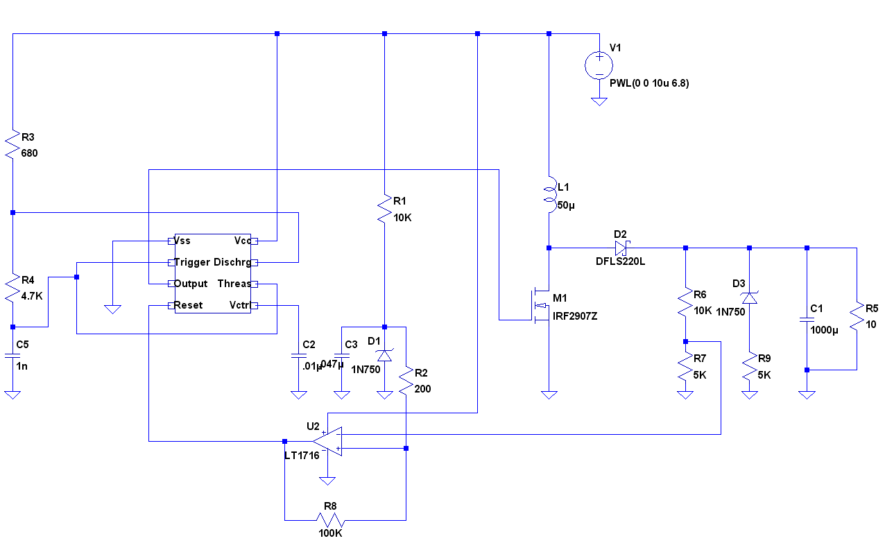
555-based boost circuit design
Reference is circuit 1 from this tutorial
Power mosfet IRF2907Z datasheet here
op-amp is LT1716

Sat Jun 15 03:28:33 PM EDT 2024
generating a 500 hz signal on a feather m4 ...
start with silly blink example
.002 second delay ...
Tue Jun 18 05:51:13 PM EDT 2024
Great description of method for UV254 here: https://images.hach.com/asset-get.download.jsa?code=50588
"use a glass fiber filter with no organic binder"
As well as here: https://assets.thermofisher.com/TFS-Assets/LPD/Application-Notes/an_uva_e_1020_rev_b_rev_web.pdf
Kearns et al methods suggest 1 um filter; Looks from last link there that .45 um filters are also acceptable
Getting some good results here -- https://www.amazon.com/s?k=glass+fiber+syringe+filter&i=industrial&crid=3FR5VDYJW4RHQ&sprefix=glass+fiber+syringe+filter%2Cindustrial%2C105&ref=nb_sb_noss_1
... need to figure out what diameter filter to try
Fri Jun 28 02:33:07 PM EDT 2024
Another 555 boost circuit here
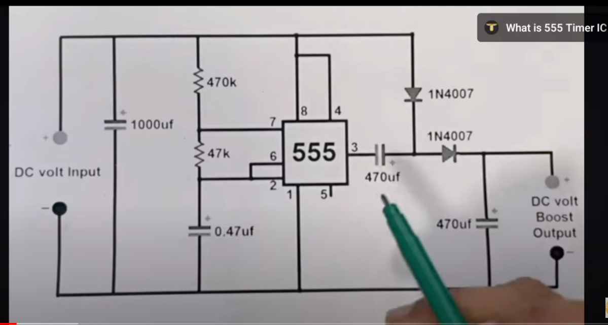
And yet another here: https://www.instructables.com/Simple-DC-DC-Boost-Converter-Using-555/
https://www.researchgate.net/publication/359257240_DC_to_DC_Boost_Converter_using_555_Timer_IC
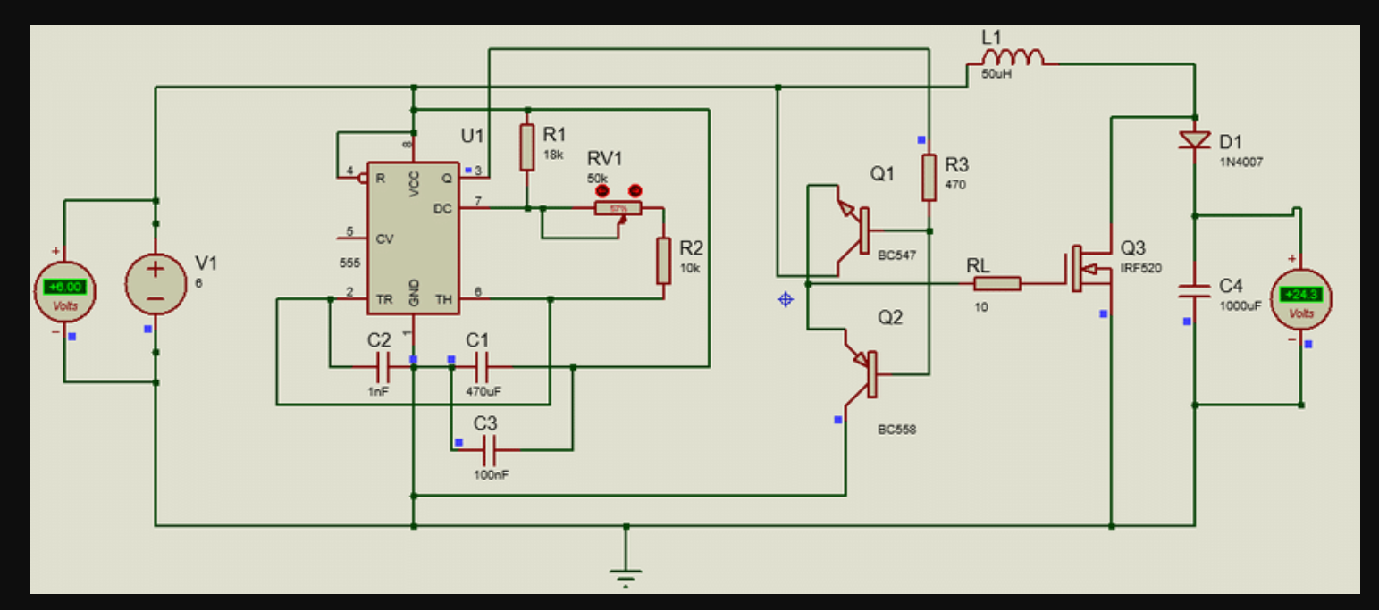
 via https://www.youtube.com/watch?v=fuXH-cQjYwo
also: https://how2electronics.com/dc-dc-converter-using-555-timer/
simplest: https://www.circuits-diy.com/boost-converter-circuit-using-555-timer-ic/
555 oscillator circuit explained here: https://www.electronics-tutorials.ws/waveforms/555_oscillator.html
simplest 555 oscillator circuit https://www.555-timer-circuits.com/simplest-555-oscillator.html
good explanation of desgining a 555 oscillator: https://www.digikey.com/en/resources/conversion-calculators/conversion-calculator-555-timer#:~:text=mS,Niobium%20Oxide%20Capacitors
BCN547 reference https://components101.com/transistors/bc547-transistor-pinout-datasheet
Sun Jun 30 05:40:21 PM EDT 2024
Used this circuit to make a mostly 50% duty cycle oscillator: https://www.electronics-tutorials.ws/waveforms/555-circuits-part-1.html -- using the 'Simple 555 Oscillator' ... could improve by using diodes in lower circuits on that page ('exact 50% duty cycle'), but waiting on diode supply. used R=5.5K, C=.1uF ... freq should be 1.3KHz, got more like 580 Hz.
Now going to try to build this: https://www.researchgate.net/profile/Muhammad-Ameer-Hamza-2/publication/359257240/figure/fig1/AS:1134177667817474@1647420436729/DC-to-DC-Boost-Converter-using-555-timer-IC-6-to-24.ppm
Review of 555 timer https://electronics.stackexchange.com/questions/152432/555-timer-boost-converter-doesnt-meet-spec
Flyback converter for dummies https://www.dos4ever.com/flyback/flyback.html -- great explanation
Nice notes on 555 boost converters https://github.com/tardate/LittleArduinoProjects/blob/master/Electronics101/555Timer/NixiePowerSupply/README.md
This instructable might be derivative https://www.instructables.com/High-Voltage-Power-Supply-for-Nixie-and-Valve-Tube/ -- with a better circuit to follow
Very clear circuit diagrams:
- https://www.instructables.com/High-Voltage-Power-Supply-for-Nixie-and-Valve-Tube/
- https://github.com/tardate/LittleArduinoProjects/blob/master/Electronics101/555Timer/NixiePowerSupply/README.md
this seems like a very similar circuit https://www.eleccircuit.com/wp-content/uploads/2012/08/dc-to-dc-converter-using-ic-ne555.jpg
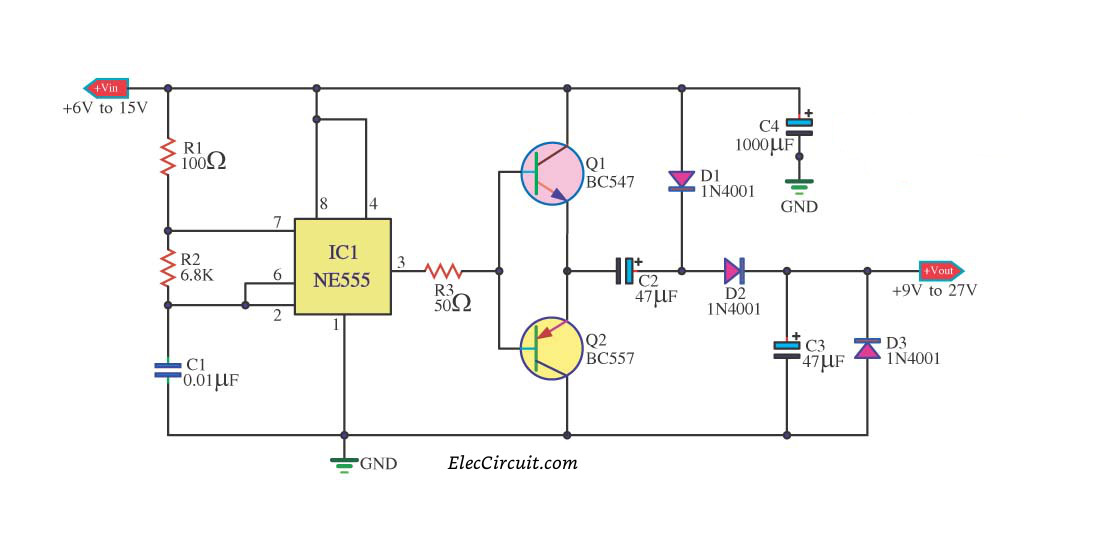
problem -- if use single 555, the output voltage will drop as the battery voltage drops. using another 555 can compensate. https://www.eevblog.com/forum/beginners/boost-converter-using-555/
... unless, i think, there's some feedback mechanism -- which an op-amp, or another 555, can provide.
Mon Jul 1 05:23:37 PM EDT 2024
Might try the IRF740 as a power mosfet ... https://www.vishay.com/docs/91054/91054.pdf
why / why not use an op-amp as a comparator? nice app note: https://www.analog.com/media/en/technical-documentation/application-notes/an-849.pdf
second circuit uses the BC557 PNP transistor https://www.mouser.com/datasheet/2/308/BC556BTA_D-2310029.pdf
trying the first circuit
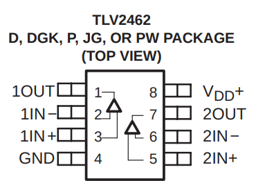
using the tlv2462 as a comparator, datasheet here

Post debug with Mike:
-
replaced IRF29072 with IRF740
-
for voltage ref, replaced 1N750 with 1N4732A (4.7V) Zener ... 4.7V was too close to 5V ... so then used 1N4727A (3V) Zener ... whatever voltage we generate via D1, implies proper value of voltage divider R6 & R7 to get us to 7.5 Volts
-
Remove D3 & D9
-
Place C3, but might not need to populate
-
replaced DFLS220L with IN5817
-
tested with 3 x 1K resistor load in parallel (replacing R5); still very smooth output, no droop
Tue Jul 2 05:26:31 PM EDT 2024
LM358ADR digikey $0.40 here
Package: 8-SOIC (0.154", 3.90mm Width)
What input voltage is ideal for the LEDs?
Try to get to 7.5 volts ...
Okay ...
Got to 7.5 volts with the combination I have
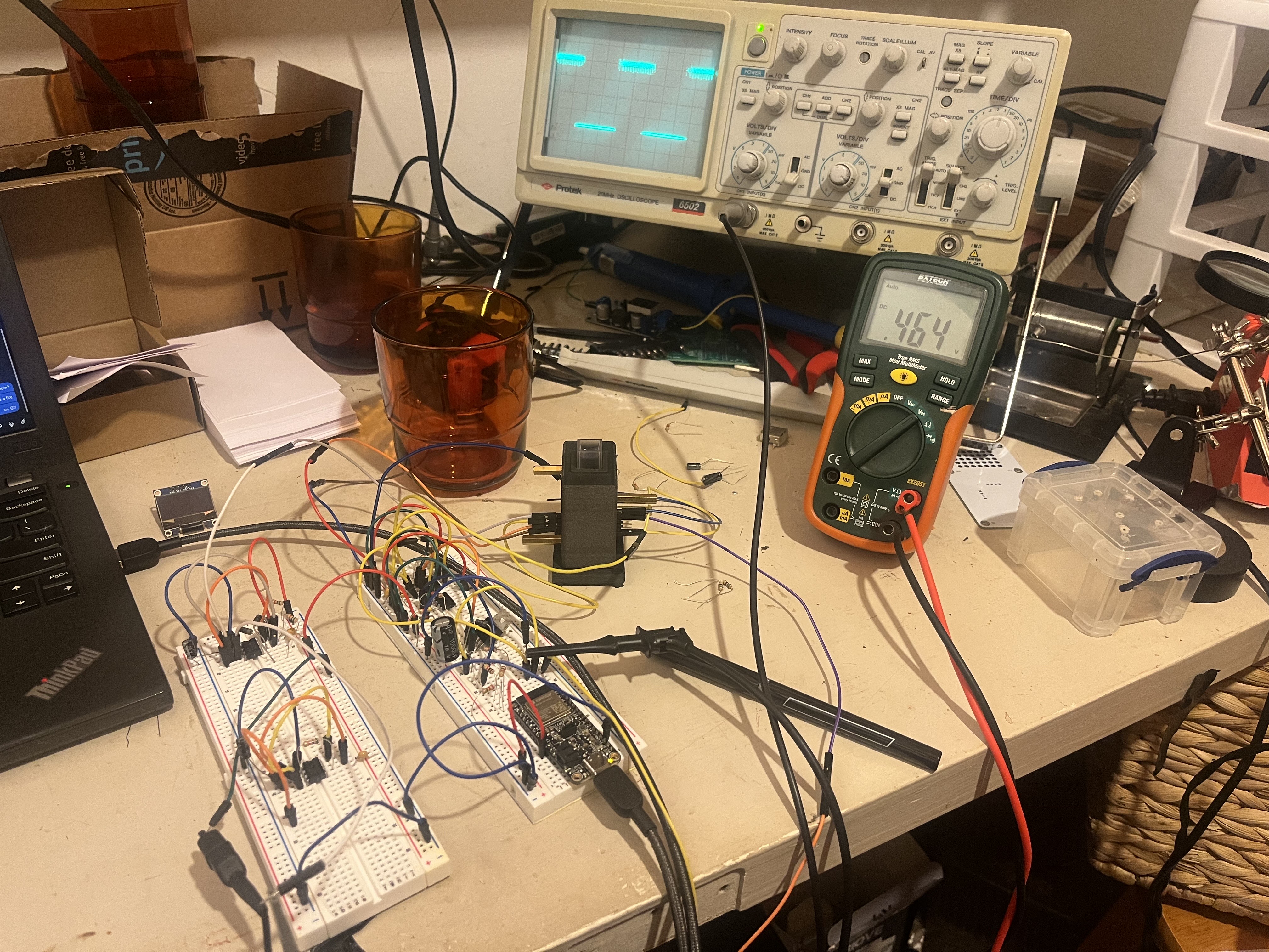
Replicated the basic setup with 555 timer input, using this circuit as a reference:
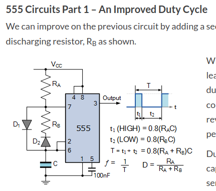
Reference: see "555 Circuits Part 1 – An Improved Duty Cycle" , at https://www.electronics-tutorials.ws/waveforms/555-circuits-part-1.html
Used: NE555 timer, RA = RB = 5.5K; C = 0.1 uF; got freq of 1.15 kHz; used 100 nF from pin 5 to ground
555 output was a little noisy / shaky, not sure whether that's important / something to address.
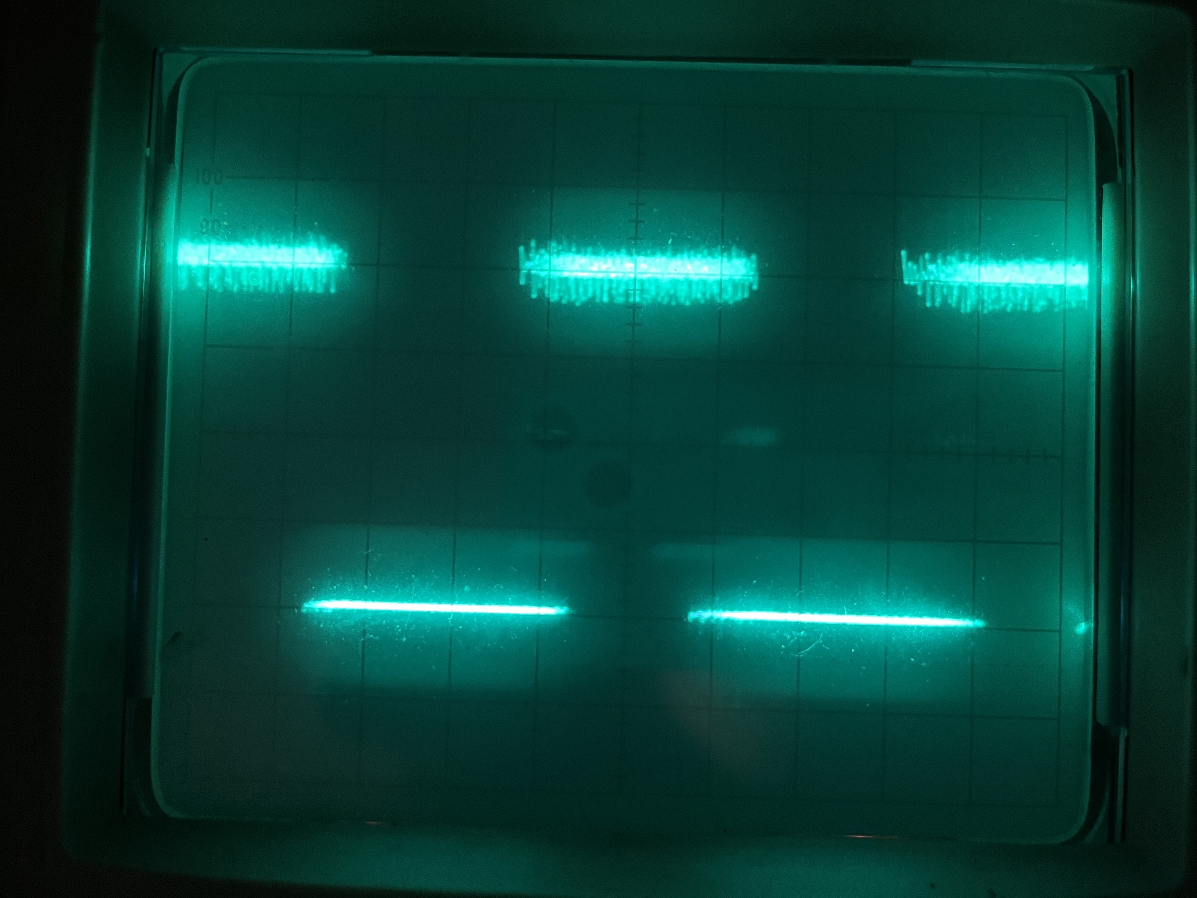
1.15 kHz seemed to result in stronger detector signal than 660 Hz, from what I could tell ...
Meanwhile, the circuit I'm using to generate 7.5 volts is the first circuit here
- Used LM358P for comparator
- Used NE555 for 555
- R1 is 10K
- D1 is a 1N4727A ... the voltage drop across it seemed to be around 2.2 V
- R6 is 10K (9.69K when measured)
- R7 is 4.2K
- replaced IRF29072 with IRF740
- Remove D3 & R9
- Place C3, but might not need to populate
- replaced DFLS220L with IN5817
seemed to generate around 7.5 volts. Might want to place an optional potentiometer to dial in the proper voltage ...
Wed Jul 3 05:27:24 PM EDT 2024
Reading about output filter design here: https://resources.altium.com/p/switching-power-supply-output-filter-design-and-simulation
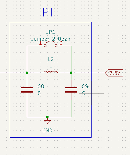
Added 10uF cap from 5V to GND, and added 50 uH inductor across 5V output ...
Switching 555 is running at 155 KHz
Current signal gen 555 output is at 880 Hz
Designing a snubber circuit for a buck IC: https://fscdn.rohm.com/en/products/databook/applinote/ic/power/switching_regulator/buck_snubber_app-e.pdf
Minimizing ringing of a boost converter: https://www.ti.com/lit/an/slva255/slva255.pdf?ts=1720022648821
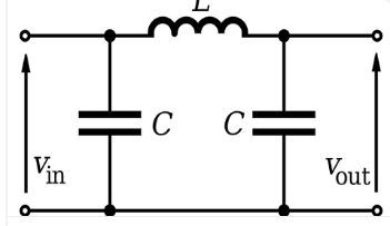
Pi filter: https://diyguru.org/term/what-is-a-pi-filter/
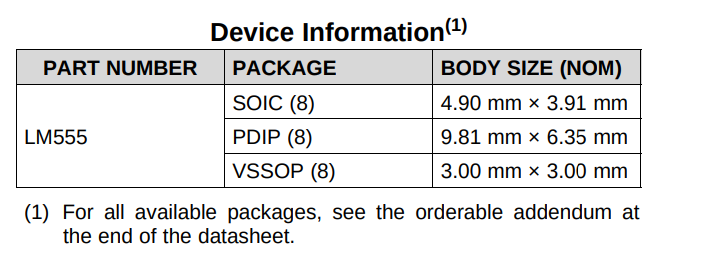
via LM555 datasheet
SOIC-8 -- 4.90 mm × 3.91 mm
RC snubber around a Mosfet
Fri Jul 5 06:07:37 PM EDT 2024

What to do with unused op-amps https://e2e.ti.com/blogs_/archives/b/thesignal/posts/the-unused-op-amp-what-to-do
Selecting the right comparator https://www.analog.com/en/resources/technical-articles/selecting-the-right-comparator.html
Reference around designing snubber circuits https://www.cde.com/resources/technical-papers/design.pdf
TL331IDBVR -- the single comparator version of the lm339 -- https://www.digikey.com/en/products/detail/texas-instruments/TL331IDBVR/381307
Suggested power mosfet here: https://www.digikey.com/en/products/detail/diodes-incorporated/DMN61D9UWQ-13/7666847
-- to be determined, as long as there's a proper footprint
going for this for now https://www.diodes.com/assets/Datasheets/DMN2056U.pdf -- final is the DMN2056U
QT-PY details https://learn.adafruit.com/adafruit-qt-py/downloads
test point https://www.digikey.com/en/products/detail/keystone-electronics/5001/255327
Thu Jul 11 04:35:04 PM EDT 2024
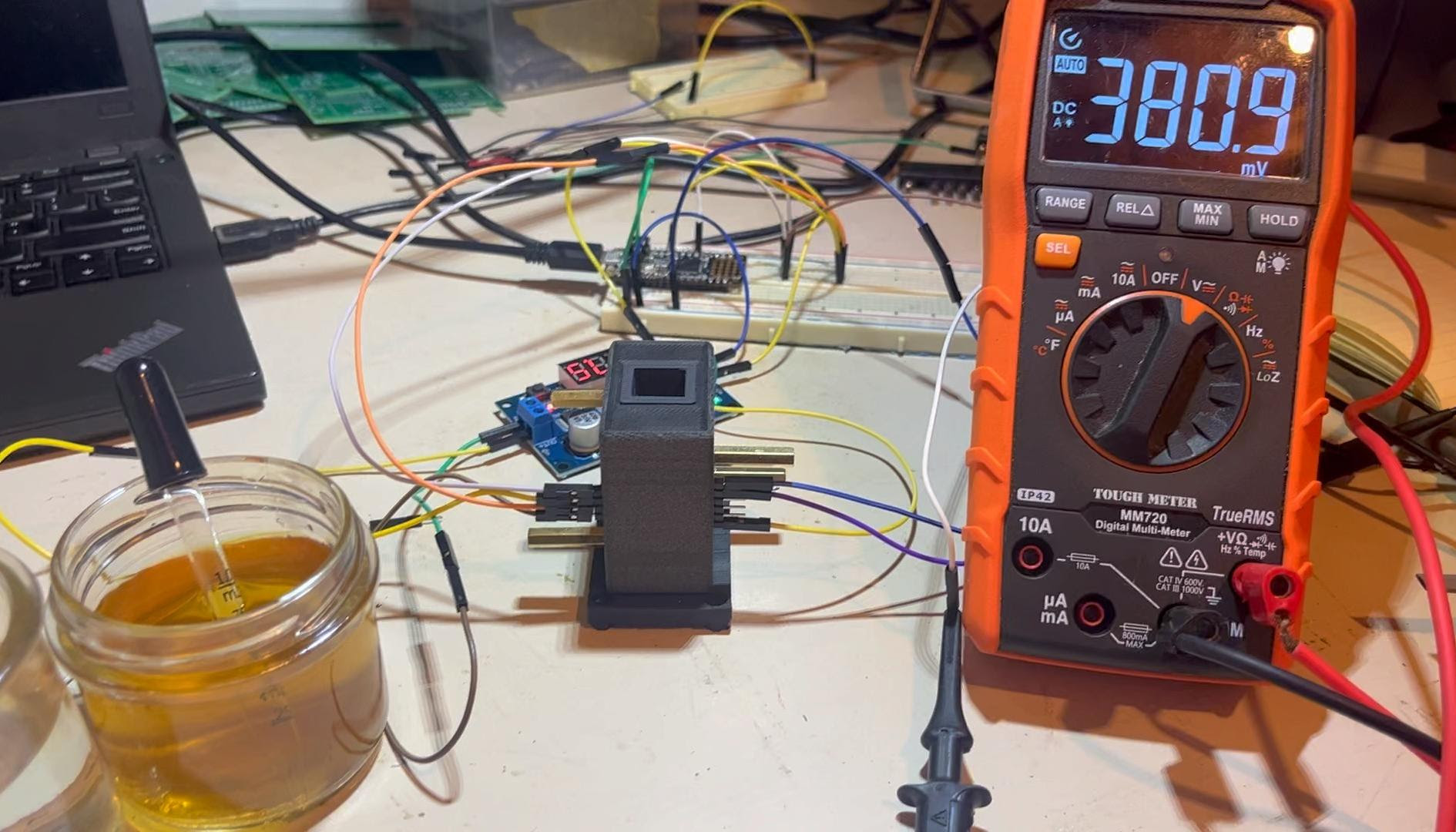
Previous linearity evaluation
Previous linearity test, using multimeter to measure outout of 'DETECT', and wine tannins:
Addressing fluctuating ADC measurement
Fixing the fluctuating signal on the ADC Feather input by adding an RC filter (R=5.5K, C=330nF, placed right at ADC input)
 |
|---|
| 0.1uF or 1uF cap only |
 |
|---|
| RC filter (R=5.5K, C=330nF) on breadboard; 4 inch wire then connects to Feather ADC. |
 |
|---|
| RC filter (R=5.5K, C=330nF) with cap placed directly at Feather ADC |
Summary: fluctuating ADC measurements seem to have been due to boost generator pulses being picked up by ADC. Adding RC filter squashed it, made ADC much more stable. Further improvements might involve measuring just after the 555 pulses, to avoid any influence of 555 signal.
Fri Jul 12 08:05:59 PM EDT 2024
added measurement 'solid' to Craig's openscad model:
//PCB_PCB = COLUMN_DEPTH-(PCB_STAND_OFF_DEPTH); PCB_PCB = COLUMN_DEPTH - PCB_THICKNESS*2; translate([-COLUMN_WIDTH/2,-PCB_PCB/2,0]) color("blue",0.6) cube([COLUMN_WIDTH,PCB_PCB,COLUMN_HEIGHT]);
echo(PCB_PCB=PCB_PCB);
where PCB_PCB is the distance between the inner surfaces of the emitter and detector PCBs
seems to work well

and the measured distance is 23.9 mm
so in the control board design, use this distance, plus any offset due to right angle headers
Sat Jul 13 07:34:03 PM EDT 2024
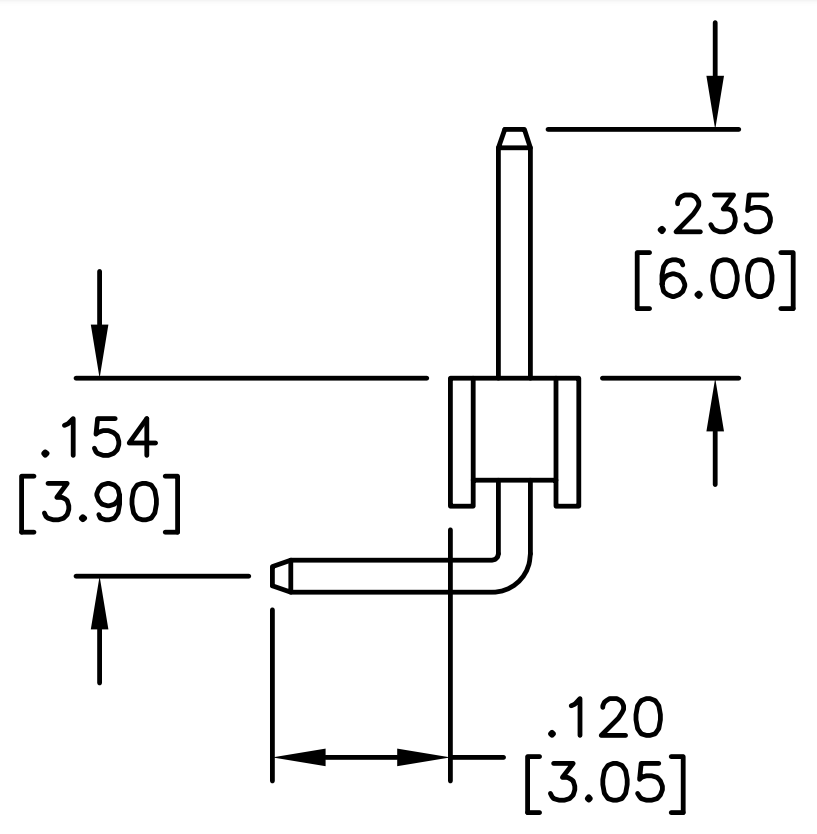
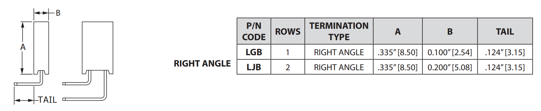
Right angle header dimensions; datasheet
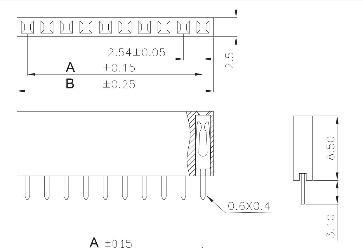
Female header: datasheet
Sun Jul 14 07:48:14 PM EDT 2024
Right angle female header:
- datasheet
- pic:
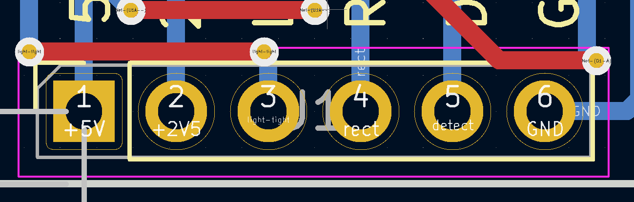
Detector pinout:
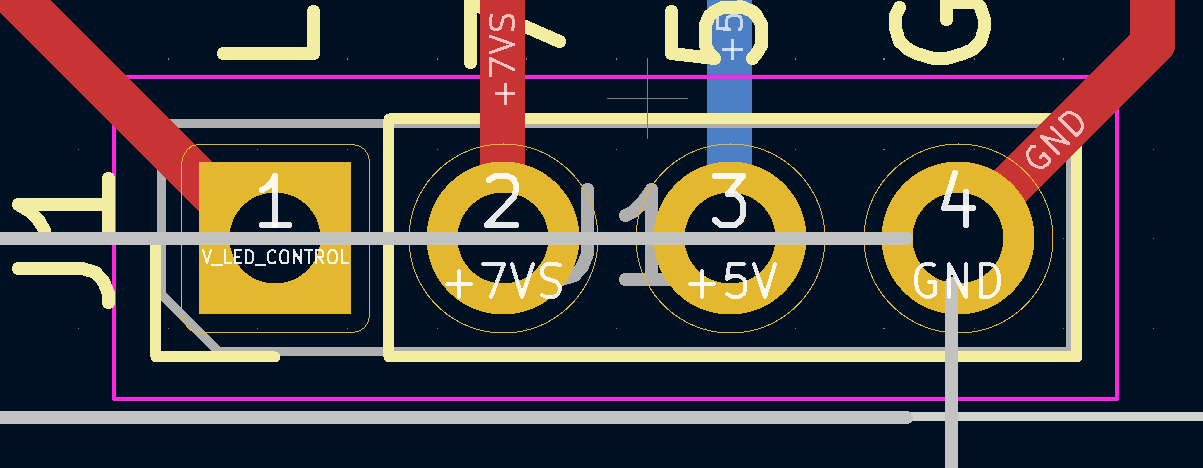
Emitter pinout:
COLUMN_WIDTH=44 mm
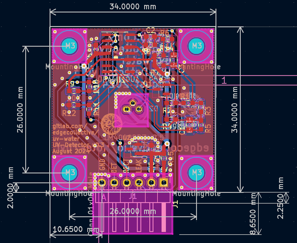
i.e. the emitter and detector pcbs are 34 mm x 34 mm; the current 'column' 3d design is 10 mm wider than the pcb
if we want the connectors to be separated by an integral number typical header spacings, we can do 12; i.e. 12*2.54 mm = 30.48
detector header is at 29.62;
Tue Jul 16 07:12:13 PM EDT 2024
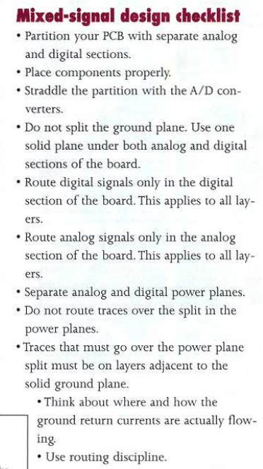
Partitioning and layout of mixed-signal PCBs here
Ground pours in KiCad here
D1 -- Zener diode -- Need to use 3V zener ; for example, MMSZ4683-TP -- SOD123 seems like typical footprint?
D4 -- Schottky diode, e.g. SM5817PL-TP ... SOD123FL
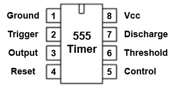
555 timer -- e.g. NE555DR -- 8-SOIC
inductor 50uH -- e.g. SRR1205-500YL
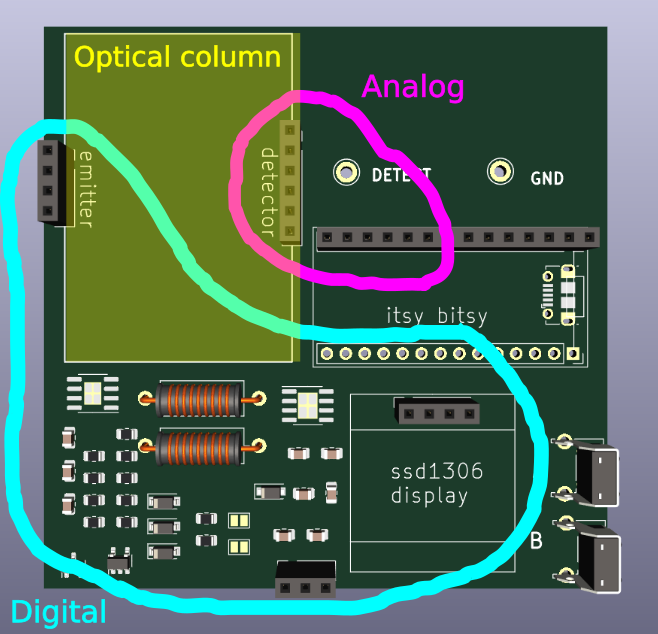
Proposed division of signals on board:

Better version:
REMINDER: need to add RC low-pass filter on top of analog input in 'motherboard'
Fri Jul 19 06:44:38 PM EDT 2024
Switch on/off drawing here

Mon Jul 22 09:53:46 PM EDT 2024
Tue Oct 8 07:01:59 PM EDT 2024
optical_column_pcb_3.scad: